Load introduction structure, in particular a lining frame, for an aircraft

Inactive Publication Date: 2010-02-18
AIRBUS OPERATIONS GMBH
View PDF16 Cites 5 Cited by
  • Summary
  • Abstract
  • Description
  • Claims
  • Application Information

AI Technical Summary

Benefits of technology

[0006]It is therefore the object of the invention to produce a lining frame for an aircraft, in particular a cargo aircraft, which, at maximum load bearing capacity, enables useful loads, in particular people or the like, to be safely secured in place in the fuselage airframe, in particular in the direction of flight (

Problems solved by technology

Aircraft, in particular transport aircraft, are exposed to considerable structural and thermal loads during operation.
However, due to the aforementioned operation-induced changes in length of the fuselage airfra

Method used


Image

  • Load introduction structure, in particular a lining frame, for an aircraft
  • Load introduction structure, in particular a lining frame, for an aircraft
  • Load introduction structure, in particular a lining frame, for an aircraft

Examples


Example

DETAILED DESCRIPTION OF THE DRAWINGS

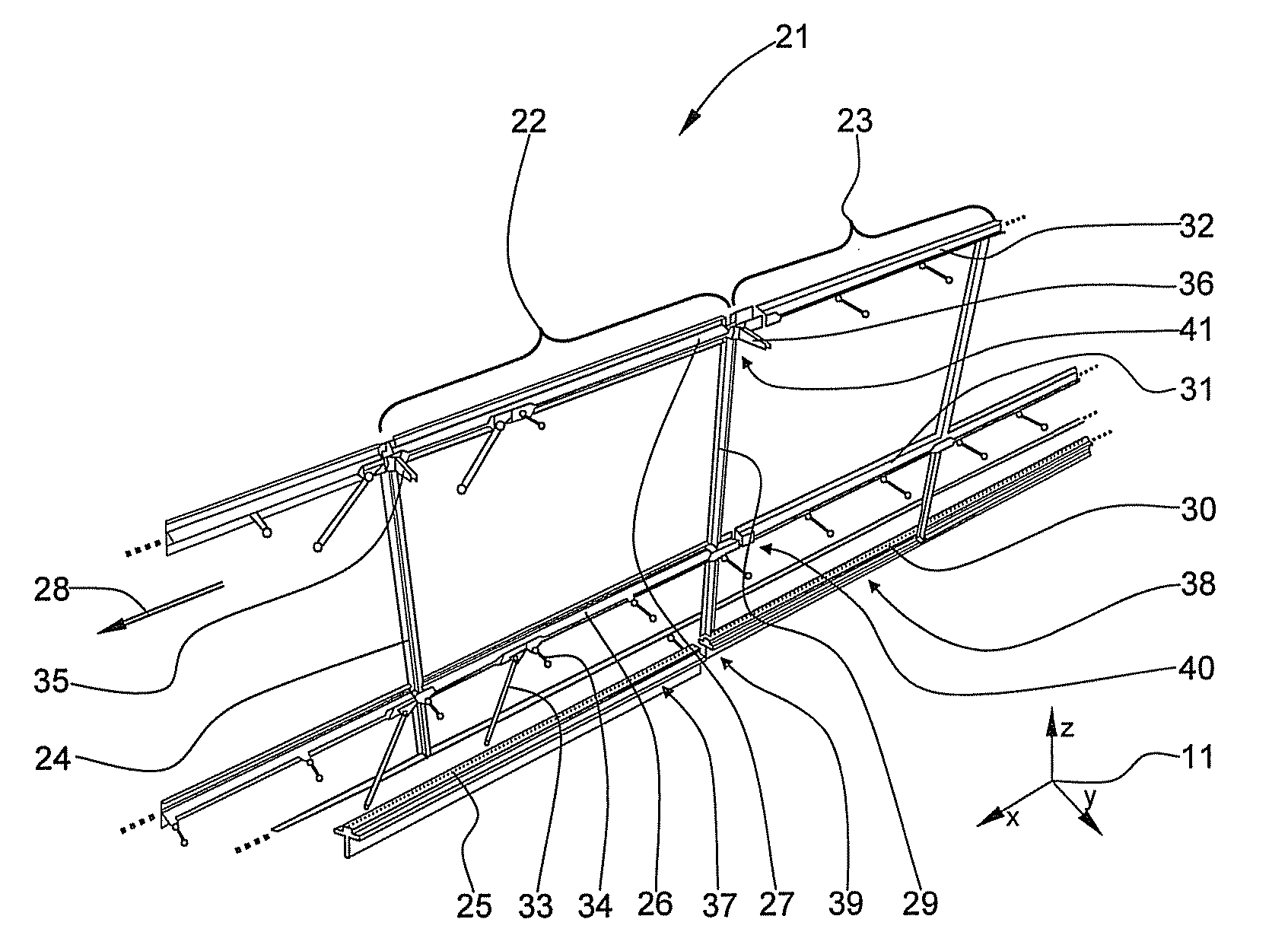
[0020]In the drawings, functionally equivalent elements which are repeated a number of times, such as ring frames, stringers or (connection) rods for connecting structural components, fastening means or the like are generally provided with only one reference numeral if there is no difference between them.

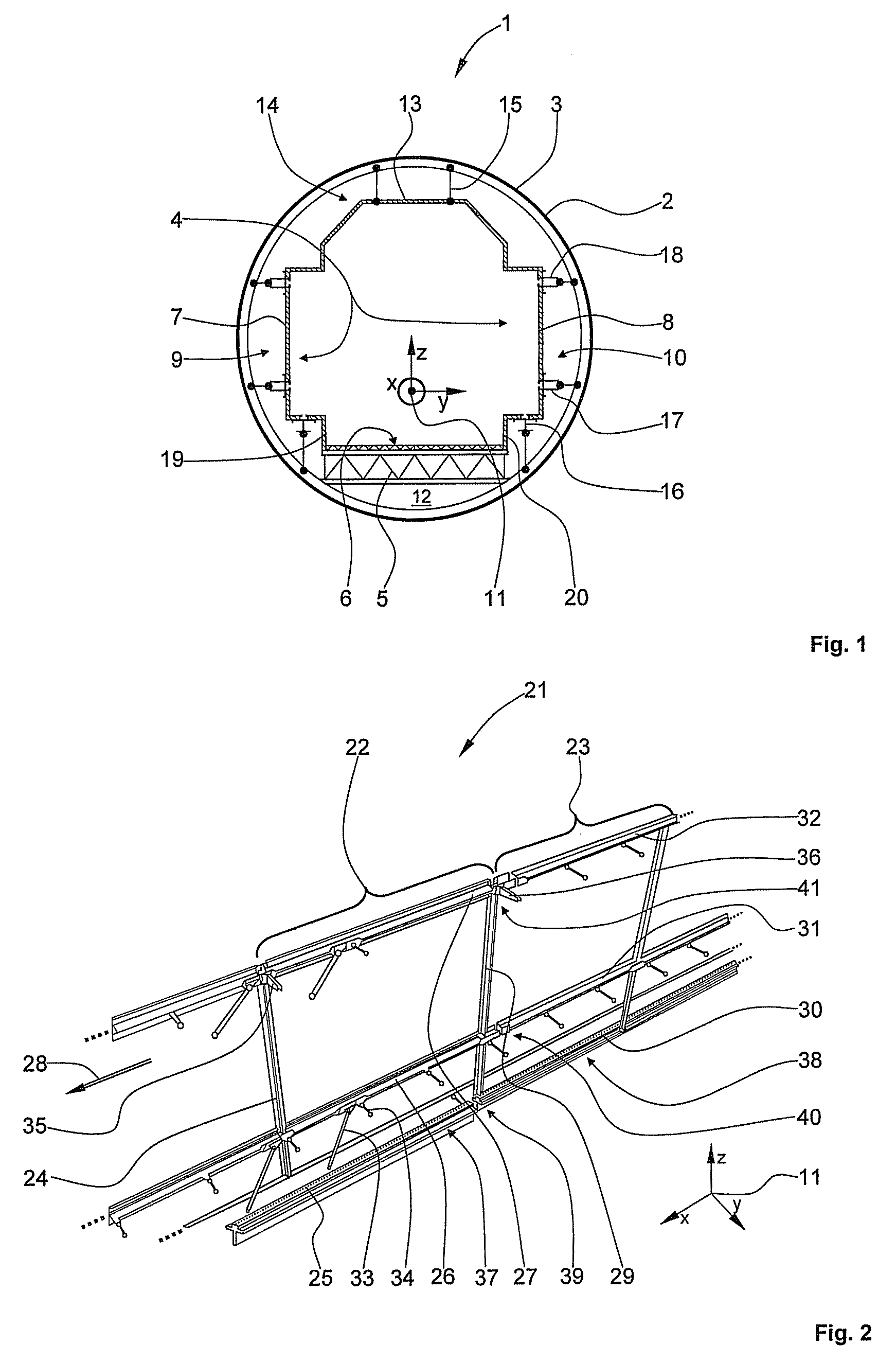
[0021]FIG. 1 shows a schematic cross-section through a lining frame.

[0022]A fuselage airframe structure 1 is formed by a plurality of ring frames 2 arranged in succession. The ring frames 2 are covered by a fuselage airframe 3 to form an inherently closed and pressure-tight fuselage airframe structure.

[0023]Arranged within the fuselage airframe structure 1 are a load introduction structure 4 in the form of a lining frame and a floor surface 6 resting on a floor frame 5. The load introduction structure 4 comprises two lateral frames 7, 8 which are arranged opposite one another in lateral regions 9, 10 of the fuselage airframe structure 1. A coordin...


PUM


Abstract

The invention relates to a load introduction structure for an aircraft, comprising two lateral frames which are arranged opposite one another in the two lateral regions of a fuselage airframe structure of the aircraft and adjoin a continuous floor surface which rests on a floor frame. The two lateral frames are connected via the top thereof by a ceiling frame, the ceiling frame being suspended from a ceiling region of the fuselage airframe structure. Each lateral frame is divided into at least two lateral frame segments. At least three track portions which extend parallel to a longitudinal axis of the aircraft are arranged on each lateral frame segment. The lateral frames are connected to the fuselage airframe structure, the ring frames in particular, by a plurality of x-rods, y-rods and y-cardan rods. The load introduction structure is largely uncoupled according to the invention from the fuselage airframe structure of the aircraft inter alia by a plurality of coupling members arranged between the track portions to form gaps in order to compensate for load-induced and/or thermally-induced deformations, in particular changes in length, of the fuselage airframe structure.

Description

CROSS-REFERENCE TO RELATED APPLICATIONS[0001]This application claims the benefit of U.S. Provisional Application No. 61 / 088,840, filed Aug. 14, 2008, the entire enclosure of which is herein incorporated by reference.FIELD OF THE INVENTION[0002]The invention relates to a load introduction structure, in particular a lining frame for an aircraft, comprising two lateral frames which are arranged opposite one another in the two lateral regions of a fuselage airframe structure of the aircraft and adjoin a continuous floor surface.[0003]Aircraft, in particular transport aircraft, are exposed to considerable structural and thermal loads during operation. For example, the external temperature in the region of the outer skin of the fuselage airframe may range between −55° C. and +85° C. and acceleration forces of up to 9 g may act on the useful load inside the fuselage airframe if the aircraft decelerates suddenly or carries out extreme flight manoeuvres. In fuselage airframes largely produce...

Claims


Application Information

Patent Timeline
IPC IPC(8): B64C1/00B64C1/06
CPCB64C1/066B64C1/061
Inventor BENTHIEN, HERMANNKRUSE, MICHAEL
Owner AIRBUS OPERATIONS GMBH
Why Eureka
Try Eureka