
Secondary battery module

a secondary battery and module technology, applied in secondary cell servicing/maintenance, cell components, jackets/cases materials, etc., can solve the problems of large restriction on efficiency enhancement, difficult not only to reduce the weight of secondary batteries, but to increase the efficiency of volum

Active Publication Date: 2008-05-22
HITACHI AUTOMOTIVE SYST LTD
View PDF4 Cites 14 Cited by
  • Summary
  • Abstract
  • Description
  • Claims
  • Application Information

AI Technical Summary

Benefits of technology

[0007]In view of the above circumstances, an object of the present invention is to provide a secondary battery module which is capable of securing safety at a time of abnormal battery operations by using a film-type secondary battery.
[0009]According to the present invention, at a time of ordinary operations, by the connecting member placed so as to face the single battery or the unit cell disposed at one end of the plurality of unit cells, the single battery or the unit cell disposed at one end of the plurality of unit cells is connected to the external output terminal and, therefore, power from the single battery or the unit cell is output to the external output terminal. On the other hand, the pushing member is disposed between the single battery or the unit cell disposed at one end of the plurality of unit cells and the connecting member and, at a time of abnormal battery operations, that is, when the single battery or any one of the plurality of unit cells expands, the pushing member breaks off the connection established by the connecting member between the single battery or the unit cell disposed at one end of the plurality of unit cells and the external output terminal and, therefore, even when overcharge occurs (in the secondary battery module), safety of the secondary battery module can be secured.
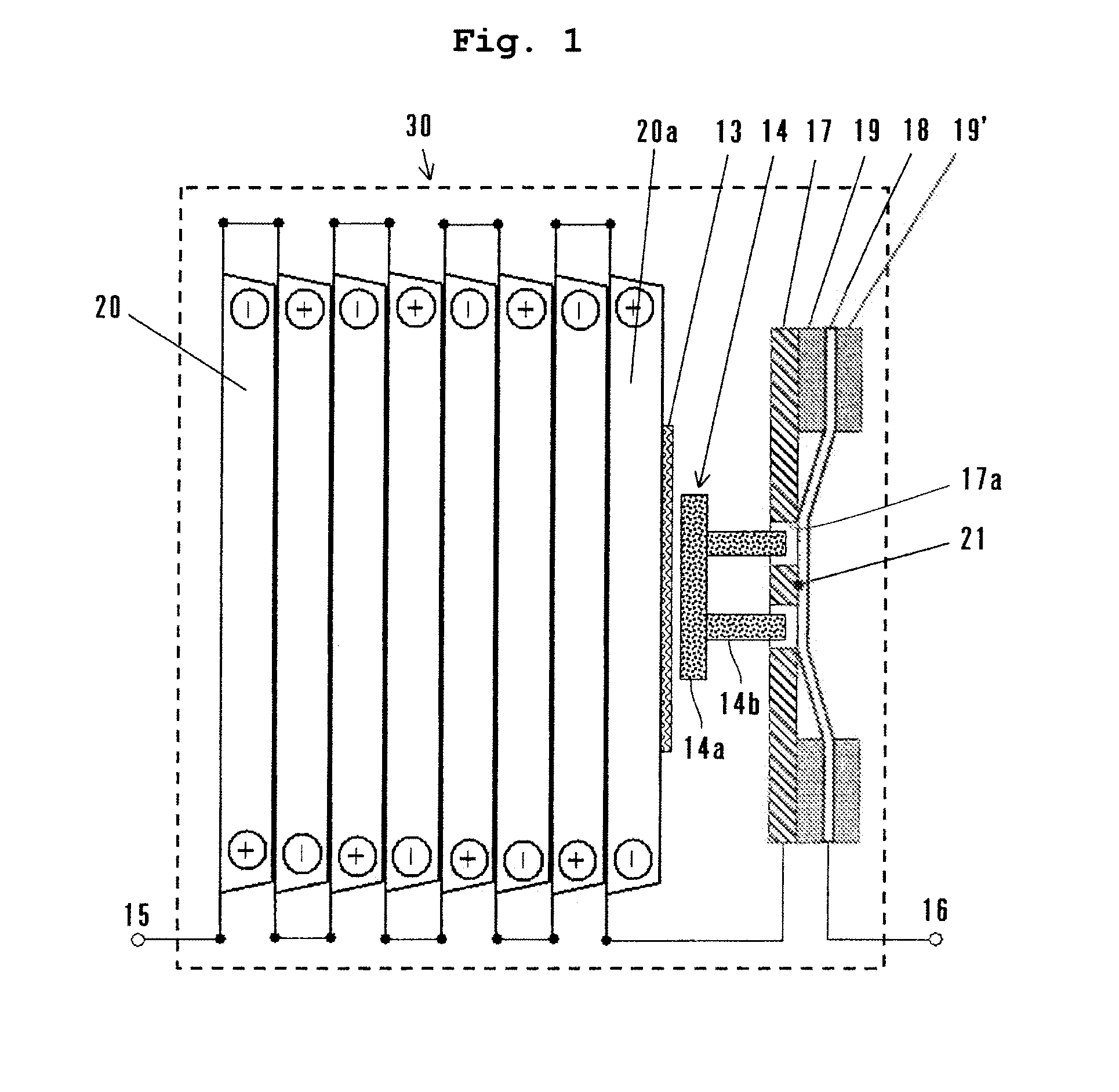
[0011]In the aspect as described above, at a time of ordinary operations, the first connecting member having through-holes being formed and placed so as to face the single battery or the unit cell disposed at one end of the plurality of unit cells is connected to the second connecting member disposed so as to face the first connecting member with the coupling portion interposed between the first and second connecting members and one of the first connecting member and the second connecting member is connected to the single battery or the unit cell disposed at one end of the plurality of unit cells and another of the first connecting member and the second connecting member is connected to the external output terminal and, therefore, power is output to the external output terminal through the first and second connecting member. On the other hand, the pushing member having projected portions able to pass through the through-holes formed in the first connecting member is disposed and, therefore, at a time of abnormal battery operations, when the single battery or any one of the plurality of unit cells expands, the projected portions of the pushing member pass through the through-holes formed in the first connecting member, causing the coupling portion between the first and second connecting members to rupture and breaking off the connection between the first and second connecting members, which enables safety of the secondary battery module to be secured.
[0014]In the aspect as described above, at a time of ordinary operations, one of ends of the connecting member having a weak portion in its partial place so as to face the single battery or the unit cell disposed at one end of the plurality of unit cells is connected to the single battery or the unit cell disposed at one end of the plurality of unit cells and another of ends of the connecting member is connected to the external output terminal and, therefore, power from the single battery or the unit cells is output through the weak portion to the external output terminal. On the other hand, since the pushing member formed in a manner to be contactable to the connecting member is placed between the single battery or the unit cell disposed at one end of the plurality of unit cells and the connecting member, when the single battery or any one of the plurality of unit cells expands at a time of abnormal battery operations, the pushing member is pushed and moved, thus resulting in the rupture of the weak portion of the connecting member and in the breakage-off of connection between the single battery or the unit cell disposed at one end of the plurality of unit cells and the external output terminal, thereby securing safety of the secondary battery module.

Problems solved by technology

However, a high specific gravity of iron constitutes a large restriction on enhancement of efficiency with respect to weight (or on achievement of lightweightness) of the secondary battery.
This problem is common in a small-sized sealed-type lead-acid battery using an injection-molded resin container; that is, there is a problem that, even in the case of using a resin, it is difficult not only to decrease the secondary battery in weight but also to increase its efficiency with respect to volume due to a wall-thickness of the container.
Moreover, in the secondary battery, if overcharge should occur due to a failure and / or misuse of a charging device or when the secondary battery is used in an atmosphere of high temperature, the secondary battery gets into an abnormal state in which its internal pressure is increased due to gas produced by vaporization, decomposition, or the like of an electrolytic solution caused by an abnormal rise of the battery temperature.
The current interrupting mechanism can be easily provided in the conventional cylindrical and sealed-type secondary battery, however, in a thin and rectangular battery using a rectangular battery can, it is difficult to mount the current interrupting mechanism therein from the viewpoint of volume efficiency.
However, the film-type secondary battery described above has a very simple structure in which a group of electrodes is covered with a film and, therefore, it is difficult to embed the current interrupting mechanism in each unit cell.
Moreover, due to flexibility of films, formation of such a step portion as described in the JP-2004-199991 is also difficult.
As a result, a problem arises that, if overcharge should occur, currents continue to flow, which makes it impossible to decrease an internal pressure thereof, causing the expansion of a battery container.
Thus, by the secondary battery module using the film-type secondary battery as described above, it is difficult to secure safety when abnormality occurs in the battery.

Method used


Image

  • Secondary battery module
  • Secondary battery module
  • Secondary battery module

Examples


first embodiment

[0020]Hereinafter, a secondary battery module of the present invention according to the first embodiment is described by referring to drawings.

[0021](Constitution)

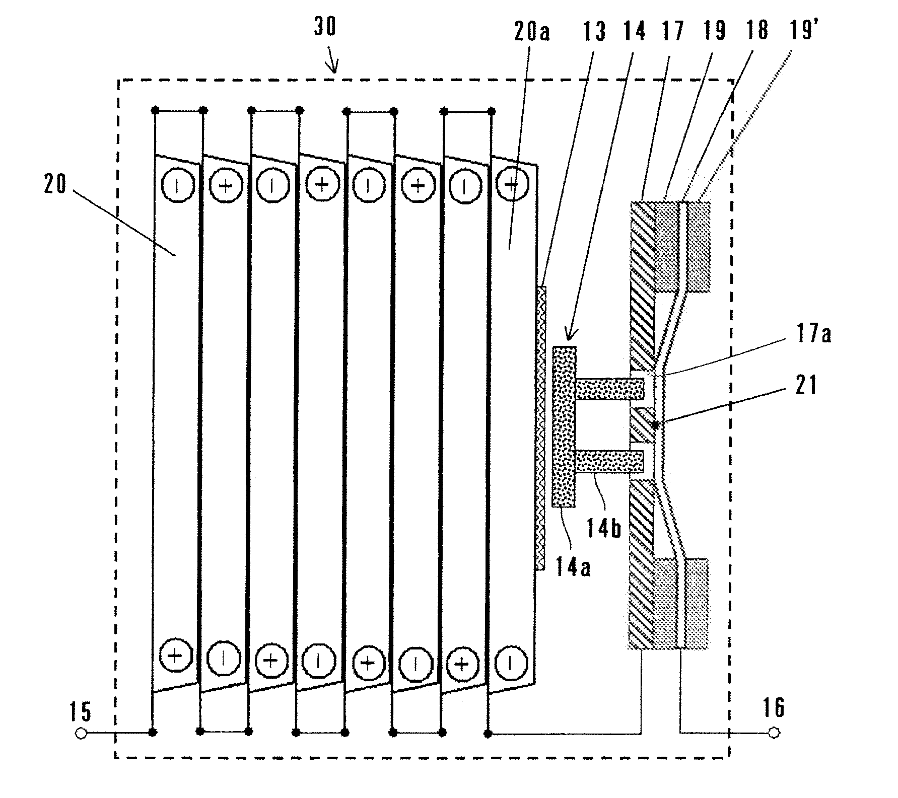
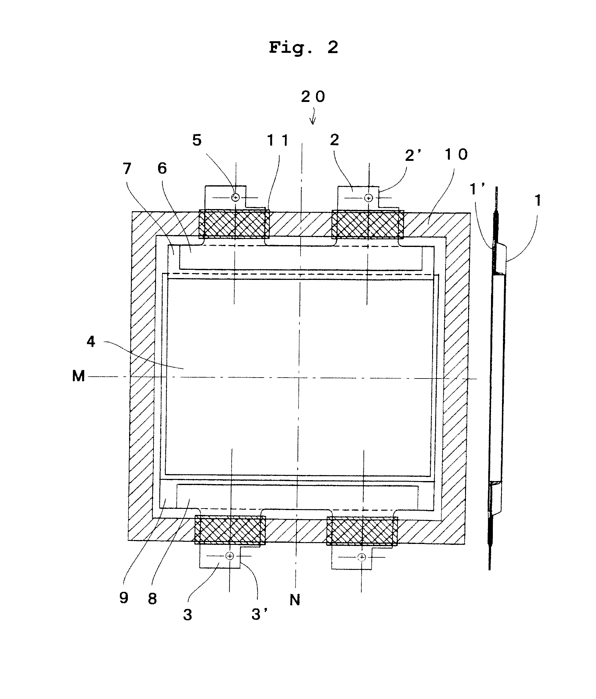
[0022]As shown in FIG. 1, the secondary battery module 30 (hereinafter, simply a “module”) of the embodiment has 8 pieces of film-type lithium ion secondary batteries 20 (hereinafter, simply as “single batteries” serving as unit cells) each using a laminate film serving as a flexible member for a battery container. In the module 30, the 8 pieces of single batteries 20 and entire components such as a connecting member or the like described later are incorporated into a frame made of an aluminum alloy (not shown).

[0023]Each of the single batteries 20 has plane portions on two surfaces facing each other. The 8 pieces of the single batteries 20 are disposed so that positive and negative electrodes thereof are arranged in an alternating manner. The plane portions of each of the single batteries 20 adjacent to one another are pl...

second embodiment

[0046]Next, a secondary battery module of the second embodiment is described below. Configurations of each of the single batteries 20 and single battery 20a and a structure in which 8 pieces of single batteries 20 are stacked of the second embodiment are the same as in the first embodiment and the same reference numbers are assigned to members or components having the same functions as in the first embodiment and descriptions thereof are omitted accordingly. Hereinafter, points being different from those in the first embodiment are explained.

[0047](Constitution)

[0048]As shown in FIG. 3, the secondary battery module (hereinafter simply a “module”) 40 is made up of 8 pieces of single batteries 20 each using a laminate film as a battery container. An entire module 40 including 8 pieces of single batteries 20 and lead plates described later is incorporated in a frame (not shown) made of an aluminum alloy. Moreover, in the embodiment, a battery capacity of the single battery 20a is 5 per...

example

[0066]Next, an example of the module 40 fabricated according to the second embodiment is described. Moreover, as a comparative example, a module was manufactured in the same method as used in the above example except that the projected portions 32 of the pushing member 24 were removed.

[0067]To check and evaluate safety of modules 40, whether or not ignition occurred when charging was performed on one hundreds of the example modules and the comparative example modules by using a regulated power source at 5 V and 1 CA (3.2 A) to the extent that overcharge occurs. The table 1 shows results from the evaluation of safety.

TABLE 1Tongue-likeprojectedportionIgnitionNo ignitionExamplepresence0100Comparativeabsence1783Example

[0068]In either of above example and comparative example modules, single batteries 20 and single battery 20a expanded due to gas generated internally and the central portions 33 of the lead plate 27 were broken and, as a result, currents are interrupted. Thereafter, in 17...


PUM

PropertyMeasurementUnit
thicknessaaaaaaaaaa
thicknessaaaaaaaaaa
thicknessaaaaaaaaaa

Abstract

The present invention provides a secondary battery module capable of securing safety at a time of abnormal battery operations by using a film-type secondary battery. A module 30 is provided with 8 pieces of single batteries 20 each using a laminate film as its battery container. The 8 pieces of single batteries are disposed in a layer-stacked state. A conducting plate 17 is placed in a manner to face one single battery 20a disposed at one end of the 8 pieces of the single batteries 20. A pushing member 14 is formed between the single battery 20a and conducting plate 17. A conducting plate 18 is disposed on a side of the conducting plate 17 opposite to the pushing member 14. The pushing member 14 has projected portions 14b. The conducting member 17 has through-holes 17a formed so that the projected portions are able to pass through. The conducting plates 17 and 18 are coupled by a coupling portion 21. When any one of the single batteries 20 and single battery 20a expands at a time of abnormal battery operations, the projected portions pass through the through-holes to break off the coupling at the coupling portion 21.

Description

FIELD OF THE INVENTION[0001]The present invention relates to a secondary battery module, and more particularly to the secondary battery module having a single battery housed in a battery container made of a flexible member or a plurality of unit cells each being disposed in a layer-stacked state, housed in a battery container made of a flexible member and connected to one another in series or in series and parallel.DESCRIPTION OF THE RELATED ART[0002]Conventionally, as a power source for charging or discharging large currents for pure electric vehicles (PEVs) and / or hybrid electric vehicles (HEVs), a secondary battery module made up of a plurality of cylindrical and sealed-type secondary batteries connected to one another in series or in series and parallel. Generally, for example, forty to one hundred pieces of cylindrical and sealed-type secondary batteries are used for such a power source for charging or discharging large currents.[0003]As a material for a cylindrical container f...

Claims


Application Information

Patent Timeline
Patent Type & Authority Applications(United States)
IPC IPC(8): H01M2/20H01M50/105H01M50/136H01M50/548
CPCH01M2/0207H01M2/0275H01M10/42H01M2/345H01M2/30Y02E60/10H01M50/578H01M50/105H01M50/136H01M50/548
Inventor OGUMA, MIKIOISHIZU, TAKENORI
Owner HITACHI AUTOMOTIVE SYST LTD
Learn More