Quick entry clipless bicycle pedal

a clipless, bicycle pedal technology, applied in the direction of mechanical control devices, process and machine control, instruments, etc., can solve the problems of limiting the range of motion of the foot and safety hazards, and achieve the effect of safe securing the rider's shoe, reducing the chance of injury, and easy targeting of the pedal platform

Inactive Publication Date: 2005-01-20
MENAYAN JESSE
View PDF17 Cites 15 Cited by
  • Summary
  • Abstract
  • Description
  • Claims
  • Application Information

AI Technical Summary

Benefits of technology

[0007] The present invention provides a unique clipless bicycle pedal system for safely securing the rider's shoe to the pedal by providing an easily targeted pedal platform, wherein engagement and disengagement of the rider's cleated shoe is co-axial with the pedal, resulting in a true “no look” engagement method. Additionally, the pedal provides for float incorporating axial side-to-side motion, as well as twist motion. This combined twist and side-to-side axial float provides a wide range of free motion that further reduces the chance of injury and better simulates total freedom of leg / foot joint action by not limiting joint movements to an axially fixed connection of the pedal to the rider's shoe.
[0010] It is an object of the present invention to provide a clipless bicycle pedal system having easily targeted pedal platform, wherein engagement and disengagement of the rider's cleated shoe is co-axial with the pedal.
[0014] It is a further object of the present invention to provide an infinite-sided pedal platform, which allows the shoe of a rider to engage onto the pedal over a full 360 degrees of the face of the pedal platform.

Problems solved by technology

Such twist float still limits the range of motion of the foot to twisting about a fixed point at which the shoe is attached to the pedal, however.
Typical systems which provide for single, double, and even four sided pedal platform though still require the rider to look in order to engage the shoe to the platform, which may result in a safety hazard.

Method used


Image

  • Quick entry clipless bicycle pedal
  • Quick entry clipless bicycle pedal
  • Quick entry clipless bicycle pedal

Examples


Embodiment Construction

)

[0025] The detailed description set forth below in connection with the appended drawings is intended as a description of presently preferred embodiments of the invention and is not intended to represent the only forms in which the present invention may be constructed and / or utilized. The description sets forth the functions and the sequence of steps for constructing and operating the invention in connection with the illustrated embodiments. It is to be understood, however, that the same or equivalent functions and sequences may be accomplished by different embodiments that are also intended to be encompassed within the spirit and scope of the invention.

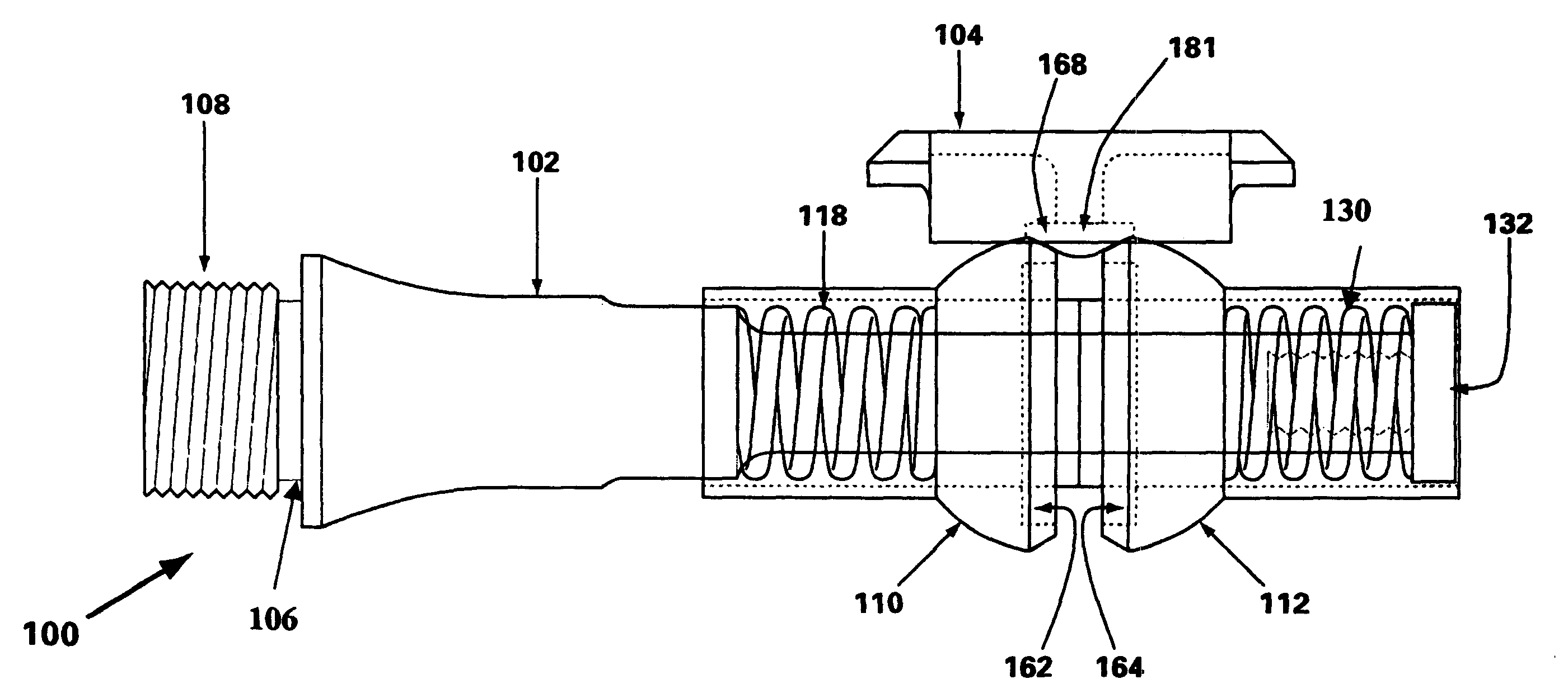
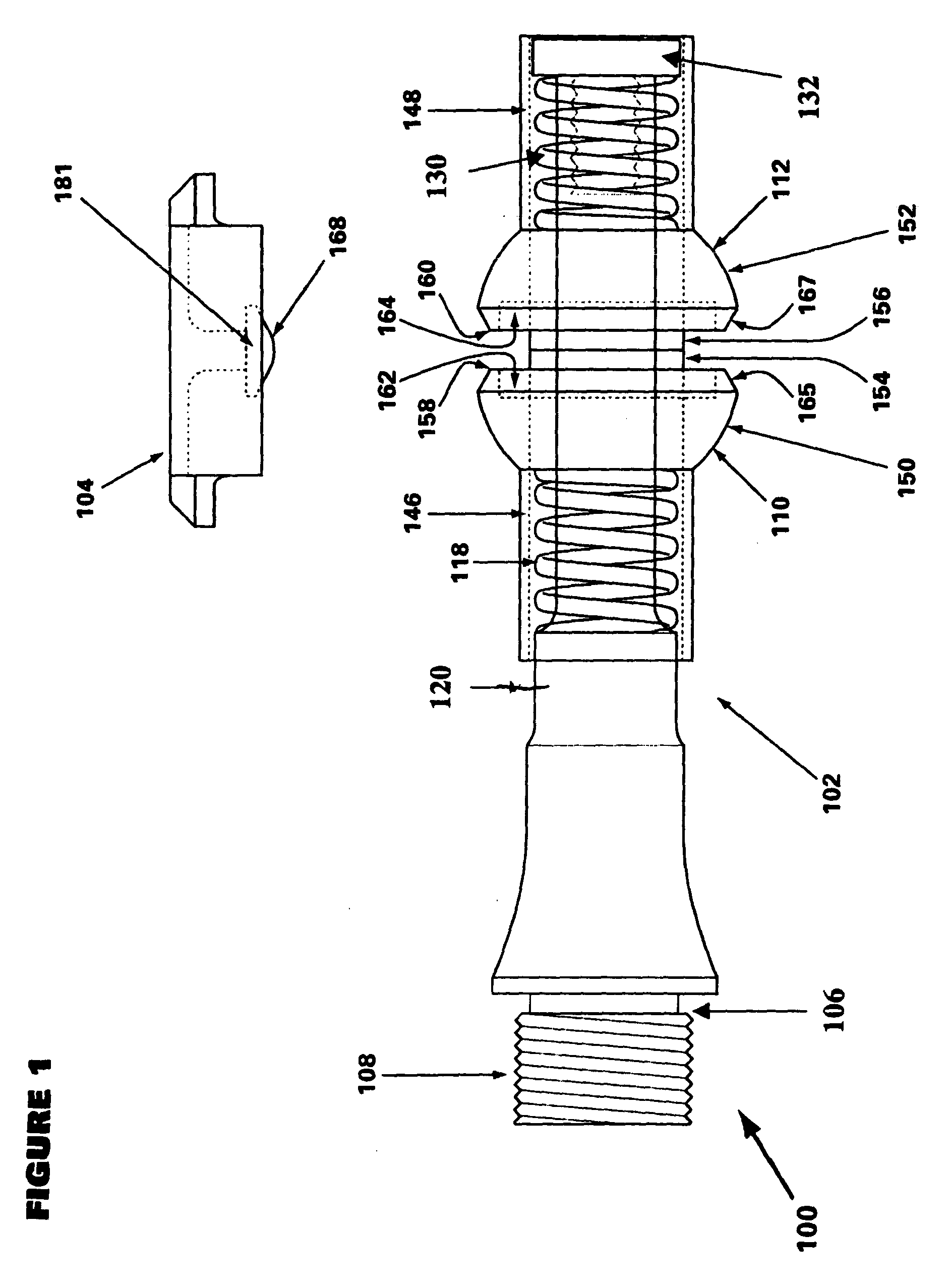
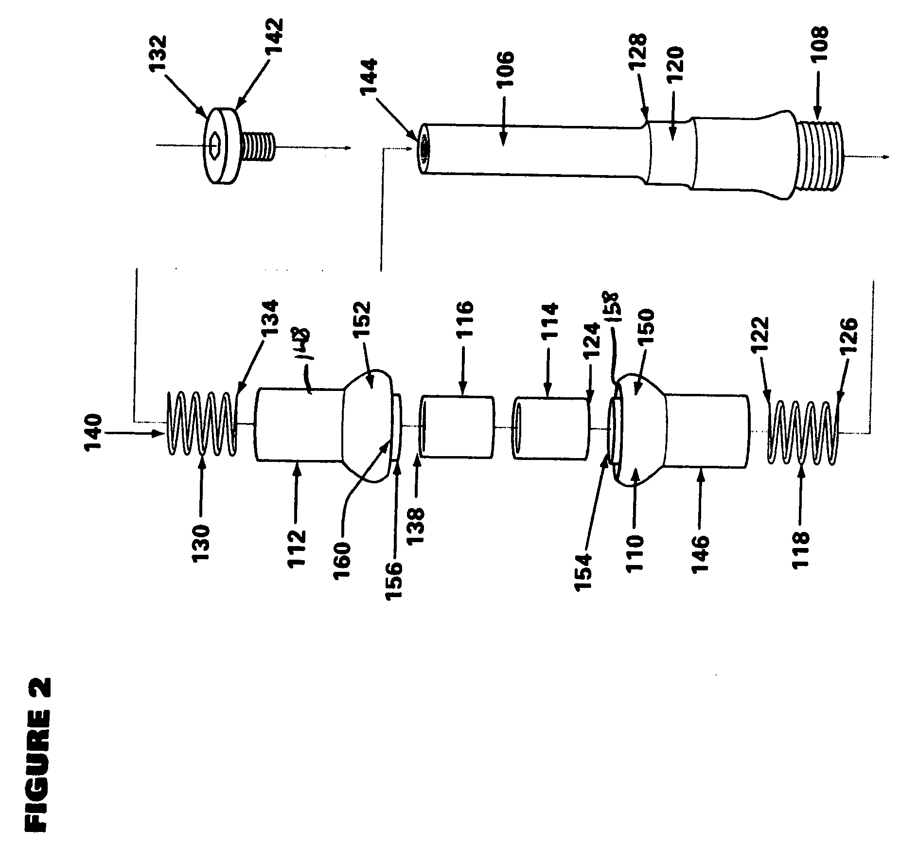
[0026] Shown in FIGS. 1-9 is a quick entry clipless bicycle pedal system 100 in accordance with a preferred embodiment, comprising a pedal 102 and cleat 104, for use with a conventional bicycle 101 and conventional bicycle shoe 103.

[0027] The pedal 102 includes a spindle 106 which attaches to the crank arm 107 of a conventional bic...


PUM


Abstract

Disclosed is a clipless bicycle pedal system for safely securing the rider's shoe to the pedal by providing an easily targeted pedal platform, wherein engagement and disengagement of the rider's cleated shoe is co-axial with the pedal, resulting in a true “no look” engagement method. Additionally, the pedal provides for float incorporating axial side-to-side motion, as well as twist motion. This combined twist and axial float provides a wide range of free motion that further reduces the chance of injury and better simulates total freedom of leg / foot joint action by not limiting joint movements to an axially fixed connection of the pedal to the rider's shoe.

Description

CROSS-REFERENCES TO RELATED APPLICATIONS [0001] This application claims priority from U.S. Provisional Application Ser. No. 60 / 415,570 filed Oct. 24, 2002, which is incorporated herein by this reference.BACKGROUND OF THE INVENTION [0002] 1. Field of the Invention [0003] This invention relates generally to bicycle equipment, and more specifically to cleat systems for bicycle pedals. [0004] 2. Description of the Related Art [0005] The past and current state of technology in the competitive cycling field has focused on the development and use of clipless bicycle pedal systems which allow for a complete securing of the shoe to the cranks and fast entry of the shoe onto the pedal. These systems typically comprise a pedal that attaches to the crank arm of the bicycle, in a manner similar to traditional bicycle pedals, and a cleat that attaches to the shoe of the rider and engages the pedal. [0006] Additionally, since there are variations in the manner in which different riders move their ...

Claims


Application Information

Patent Timeline
Patent Type & Authority Applications(United States)
IPC IPC(8): G05G1/30B62M3/08
CPCY10T74/217B62M3/086
Inventor MENAYAN, JESSE
Owner MENAYAN JESSE
Why Eureka
Try Eureka