Safety device for table saw

a safety device and cutting tool technology, applied in the field of safety systems for powered cutting tools, can solve the problems of affecting the physical injury and trauma of the hand and/or fingers of the operator, and the danger of the rotating blade or cutting element of the power cutting tool, so as to facilitate a variety of different cuts and use with different blades, and ensure the safety of the workpiece. , the effect of eliminating the kickback of the workpi

Inactive Publication Date: 2012-05-17
NIICHEL WILLIAM
View PDF11 Cites 15 Cited by
  • Summary
  • Abstract
  • Description
  • Claims
  • Application Information

AI Technical Summary

Benefits of technology

[0013]Yet another embodiment for use with table saws is, for example, in making dado cuts. The dual bearing hold down device is provided with two separate bearing elements that press the work piece in two directions to safely secure the work piece and eliminate work piece kickback. A first bearing element presses the work piece against the guide rail or rip fence, and a second bearing element presses the work piece in a perpendicular direction against the surface of the cutting table. Both bearing elements are biased against the work piece and the biasing force is adjustable. Additionally, the device itself is positionally adjustable to accommodate work pieces of different sizes. Further still, the bearing arm that positions the second bearing element may comprise different lengths to position the second bearing element at different locations relative to the cutting element, thereby facilitating a variety of different cuts and use with different blades as the situation may require.
[0014]The dual bearing hold down device may also be utilized in connection with a jointer, planer, shaper or router. In one embodiment, the dual bearing hold down device comprises a base plate that covers a substantial portion of the rotating cutting element, thereby eliminating any opportunity for the operator's hand to accidentally contact the cutting element.
[0015]A further embodiment of the present invention comprises an ant-kickback wheel. This device is contemplated primarily for use with table saws, but may also be used with other devices. In connection with table saws, the device includes a bracket or base designed to attach at or near the distal end of the guide fence with a wheel that rides on top of the work piece to provide pressure holding the work piece against the surface of the table saw and against the rip fence, greatly reducing the chance of kickback. The freely rotating wheel is adjustably positionable by a wheel bearing arm to accommodate work pieces of different thicknesses and widths and to apply adjustable pressure, as needed. The larger the diameter of the wheel, the more readily the wheel automatically engages and rides over the top of a work piece without the need for an operator to manually position the hold down wheel on the work piece, thereby eliminating the need for the operator's hand to be located near a rotating cutting instrument. The wheel bearing arm is also designed to move completely out of the way without having to dismount or disconnect the device from the equipment.

Problems solved by technology

Power cutting tools having a rotating blade or cutting element, such as table saws, miter saws, routers, jointers and shapers, are dangerous.
Thousands of operators of these types of cutting tools are severely injured every year.
It is believed that injuries resulting from use of table or cabinet-based power cutting tools other than table saws are equally significant, statistically and in the nature of the injury to the operator, but are not well reported because fewer people own and use such equipment.
The physical injury and trauma to an operator's hand and / or fingers is often significant.
Injuries occur due to several factors, including lack of understanding by the operator of the equipment and / or characteristics of the wood being cut, inattentiveness, fatigue, work piece kickback and misuse of or misplaced reliance on accessory devices such as push sticks, feather boards, splitters and kerf blades.
However, in practice, such devices do not prevent all cases of kickback and do not address non-kickback related injuries.
Moreover, they are limited to use solely with table saws and not other type of powered cutting tools.
The operator can be seriously injured by the thrown work piece.
However, serious injury also results to the operator's hand and / or fingers because, prior to the kickback event, the operator is pushing the work piece toward the rotating cutting tool.
Serious injuries can occur with each of these devices.
Attempts to develop safety devices for powered cutting tools have been made with limited success.
For example, the website www.tablesawaccidents.com / new-page-3.htm shows three safety devices which have limited applicability and usefulness.
No protection is provided to the operator's hand and use of this device requires the operator's hand to pass by the rotating saw blade.
It also limits the narrowness of a cut that can be made on a table saw due to its own width.
While it saddles and moves along a rip fence, it also provides no protection for the user's hand and only includes a single notch to accommodate a single work piece thickness.
In addition, it is not adjustable to accommodate use with guide fences of different sizes and shapes.
Indeed, the Hand Guard and Pusher Block devices depicted on the same web page could not be used with the anti-kickback devices as the forward anti-kickback device prevents the any type of pusher device from moving the work piece completely past the saw blade.
It also appears that the post cut anti-kickback device requires the operator to manually lift and position the roller on the work piece, bringing the operator's hand dangerously close to the moving saw blade.
However, this device costs hundreds of dollars and is not designed to be retrofit with existing table saws.
Further still, all of the foregoing devices are designed and intended to be used with table saws and do not address the significant and serious injuries created with miter saws, routers, jointers and shapers.

Method used


Image

  • Safety device for table saw
  • Safety device for table saw
  • Safety device for table saw

Examples


Embodiment Construction

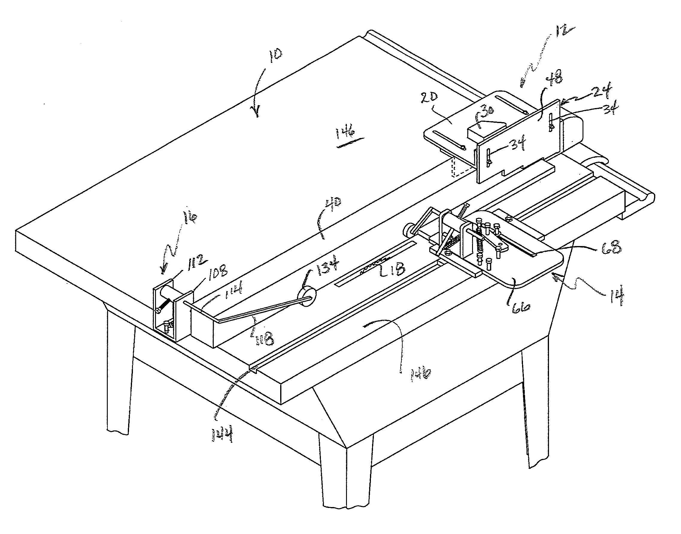
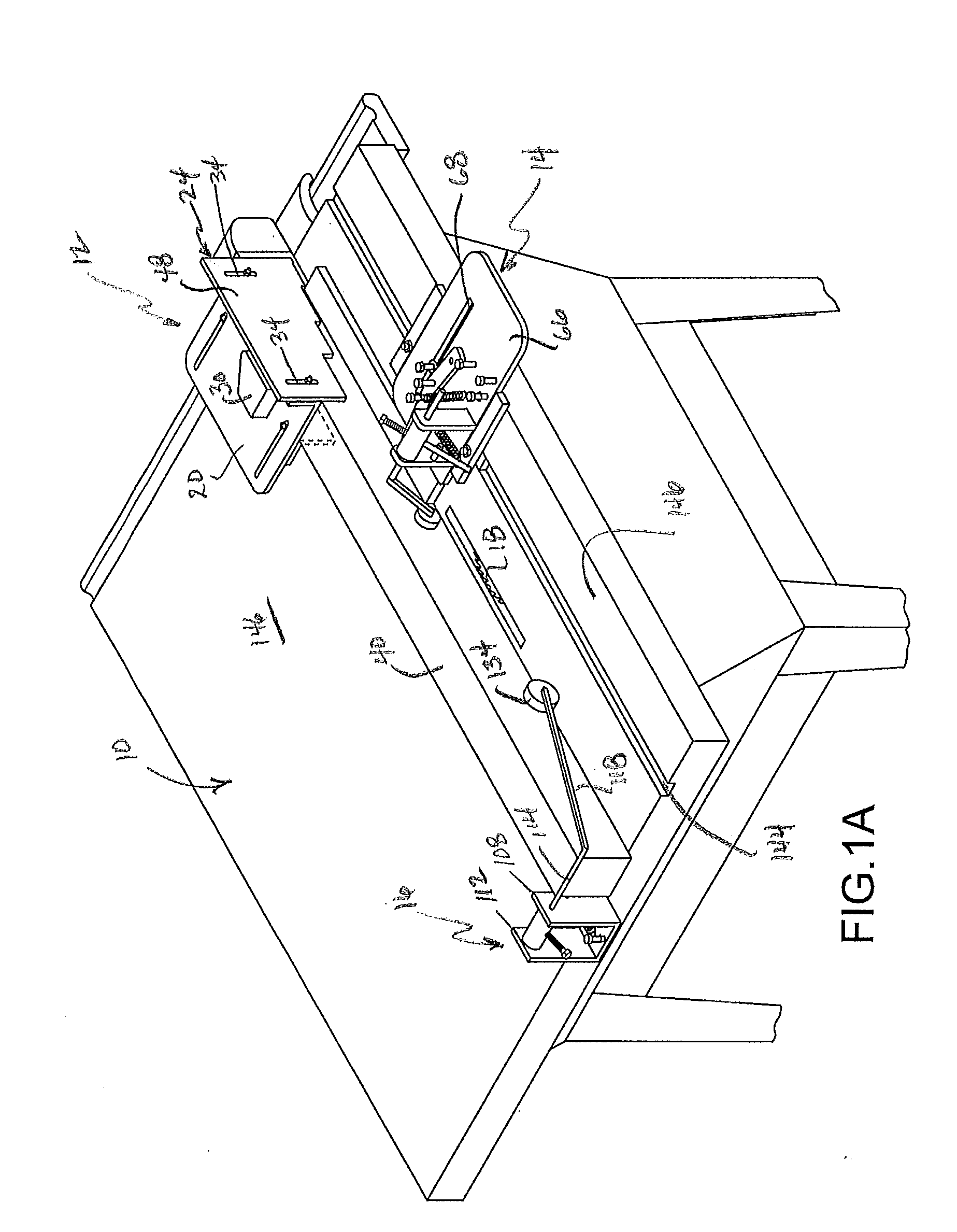
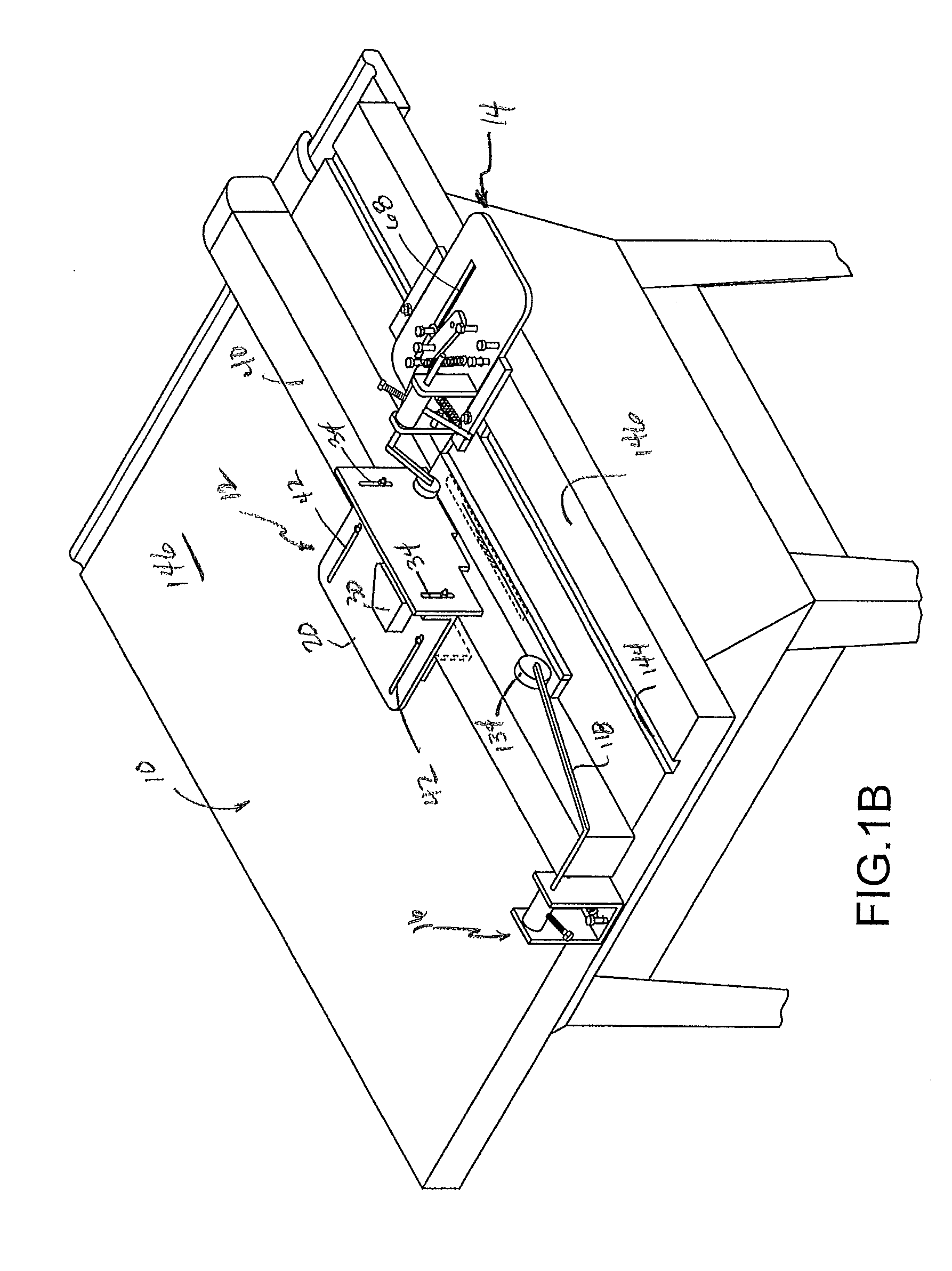
[0077]Embodiments of the safety system disclosed herein include multiple separate safety devices or components that can be used individually or in combination to enhance the safety of and reduce injuries to an operator of powered cutting tools. FIGS. 1A through 1C depict a table saw 10 with exemplary embodiments of three component devices of the overall system of the present invention. These component pieces are a right hand push device 12, a dual bearing hold down device 14, and an anti-kickback device 16. However, while the dual bearing hold down device 14 is typically positioned in front of the cutting blade 18 and the anti-kickback device 16 is typically positioned following the cutting blade 18, they are not restricted to those physical locations and may be positioned adjacent or in close proximity to the cutting blade, on opposite sides of the cutting blade or at other locations selected by those of skill in the art for purposes of enhancing safety and / or facilitating use of t...


PUM

PropertyMeasurementUnit
lengthaaaaaaaaaa
thicknessaaaaaaaaaa
diameteraaaaaaaaaa

Abstract

A safety system for powered cutting tools is disclosed. The safety system comprises a number of component devices that may be used alone or in combination to substantially reduce the risk of injury to the operator of the power cutting tool. The devices are designed for use with table saws, miter saws, jointers, routers, shapers and similar equipment. The devices secure a work piece against unanticipated movement and kickback while simultaneously protecting the operator's hands. The devices is further enhance the capabilities of power equipment to make precise cuts safer, faster and easier.

Description

CROSS-REFERENCE TO RELATED APPLICATIONS[0001]The present application claims the benefit, under 35 U.S.C. §119(e), of U.S. Provisional Application Ser. No. 61 / 413,283 filed Nov. 12, 2010 entitled “Safety Device for Table Saws,” U.S. Provisional Application Ser. No. 61 / 431,275 filed Jan. 10, 2011 entitled “Safety Device for Left-Handed Use of Table Saw,” and U.S. Provisional Application 61 / 533,663 filed Sep. 12, 2011 entitled “Adjustable Safety Device for Saws,” all of which are incorporated herein in their entirety by this reference.FIELD OF THE INVENTION[0002]The present invention relates to a safety system for powered cutting tools, primarily table saws, router tables, miter saws and planers / jointers. The system comprises a number of component devices that, alone or in combination, provide enhanced safety and reduce or eliminate injuries to an operator of the equipment. The devices attach to a frame or table associated with the powered cutting tool and are adapted for securing work...

Claims


Application Information

Patent Timeline
Patent Type & Authority Applications(United States)
IPC IPC(8): B26D7/22B27G19/02
CPCB27G19/00B27G21/00B27G19/02Y10T83/748
Inventor NIICHEL, WILLIAM
Owner NIICHEL WILLIAM
Why Eureka
Try Eureka