Stereoscopic depth mapping

a depth mapping and stereoscopic technology, applied in the field of depth mapping of stereoscopic images, can solve the problems of both compressed and distorted perception of depth

Active Publication Date: 2010-02-18
REAID INC
View PDF31 Cites 48 Cited by
  • Summary
  • Abstract
  • Description
  • Claims
  • Application Information

AI Technical Summary

Problems solved by technology

This generally results in perceived depth being both compressed and distorted producing ‘cardboard cut-outs’ and flat ‘wall-paper’ backgrounds.

Method used


Image

  • Stereoscopic depth mapping
  • Stereoscopic depth mapping
  • Stereoscopic depth mapping

Examples


Embodiment Construction

[0026]When two cameras of fixed separation capture a stereoscopic image pair from a real scene, the depth on a playback stereo display is non-linear. Uniformly-spaced objects (such as telegraph poles disappearing into the distance) appear to get closer together the further away they are. As used herein, the term “camera” refers to either a physical camera or a capture viewpoint in Computer Generated Imagery (CGI) virtual space. The present disclosure may relate to both a real-world capture environment and a CGI environment.

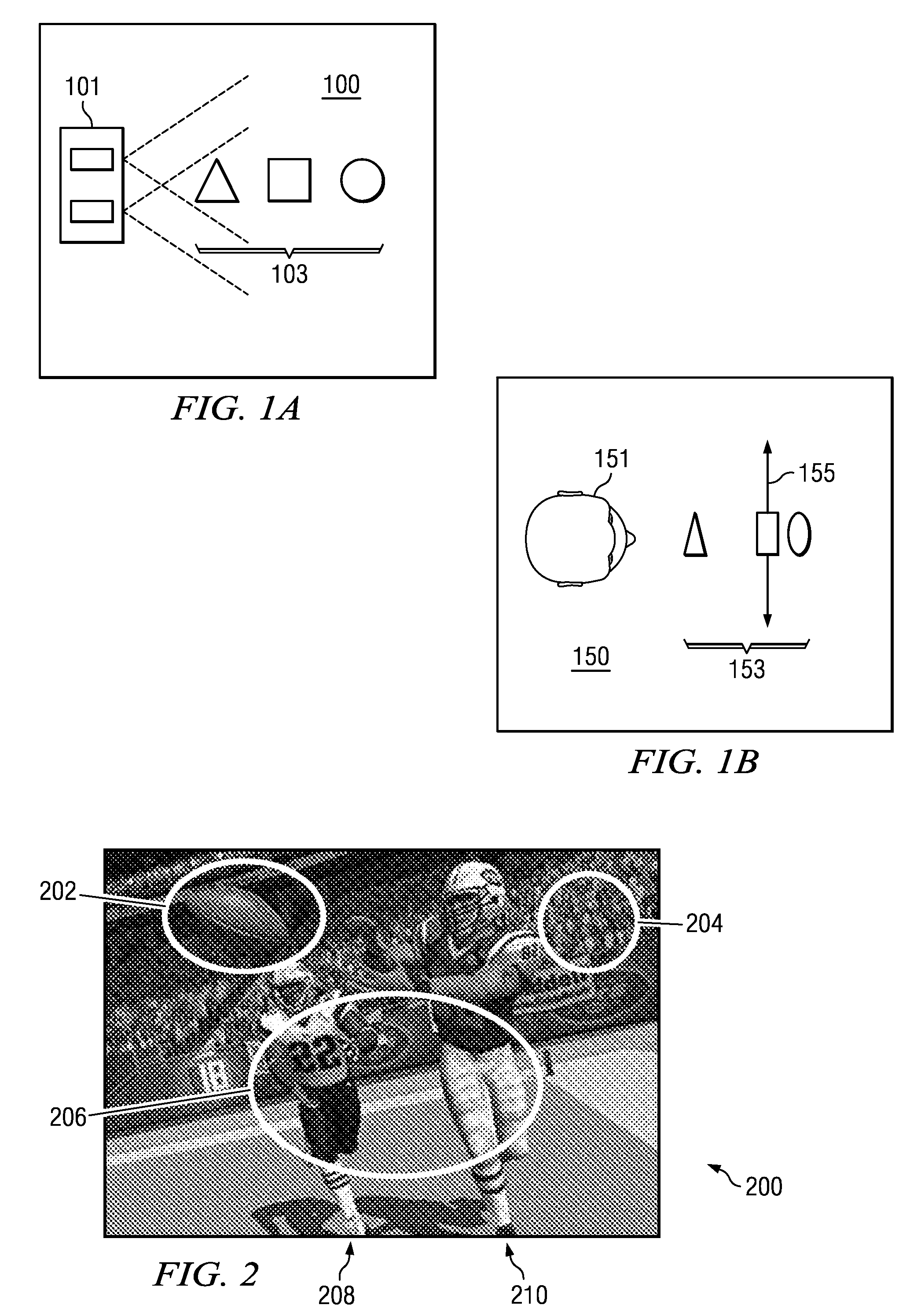
[0027]FIGS. 1A and 1B are schematic diagrams illustrating this depth distortion phenomenon. FIG. 1A illustrates the top view of a scene 100 with stereoscopic cameras 101 and substantially equally-spaced objects 103. FIG. 1B illustrates the top of the same scene as visualized on a display 150. Viewer 151 faces a display with a display plane 155, and perceives the objects 153 at a non-uniform depth.

[0028]FIG. 2 is a schematic diagram illustrating a 3-D scene 200 and...


PUM


Abstract

Provided is a method and apparatus for linear depth mapping. Linear depth mapping includes using algorithms to correct the distorted depth mapping of stereoscopic capture and display systems.

Description

CROSS-REFERENCE TO RELATED APPLICATIONS[0001]This application relates and claims priority to commonly-assigned U.S. Provisional Patent Application No. 61 / 089,018, filed Aug. 14, 2008, entitled “Linear Stereoscopic Depth Mapping,” and 61 / 102,493 filed Oct. 3, 2008, entitled “Optimal depth mapping,” both of which are incorporated herein by reference for all purposes.TECHNICAL FIELD[0002]This disclosure relates generally to stereoscopic three-dimensional (3D) imagery and, more specifically, to depth mapping for stereoscopic images.BACKGROUND[0003]Stereoscopic capture and viewing has been commonplace since Charles Wheatstone invented the Stereoscope in 1833 as discussed in On Some Remarkable, and Hitherto Unobserved Phenomena of Binocular Vision (Part the First), Wheatstone, Charles, Phil. Trans. Roy. Soc. Lon. pp. 371-394 (1838). Similar to the present day ViewMaster®, this Victorian device uses two still camera images which are seen independently by a viewer's eyes. The spatial separa...

Claims


Application Information

Patent Timeline
Patent Type & Authority Applications(United States)
IPC IPC(8): H04N13/02G06T15/20H04N13/239
CPCG06T7/0075G06T15/20G06T2207/10012H04N13/0296H04N13/0239H04N13/0246H04N13/0022G06T7/593H04N13/128H04N13/246H04N13/296H04N13/239
Inventor ROBINSON, MICHAEL G.
Owner REAID INC
Why Eureka
Try Eureka