Management of power domains in an integrated circuit

Active Publication Date: 2010-02-18
NXP USA INC
View PDF6 Cites 39 Cited by
  • Summary
  • Abstract
  • Description
  • Claims
  • Application Information

AI Technical Summary

Problems solved by technology

This fixed response re

Method used


Image

  • Management of power domains in an integrated circuit
  • Management of power domains in an integrated circuit
  • Management of power domains in an integrated circuit

Examples


Embodiment Construction

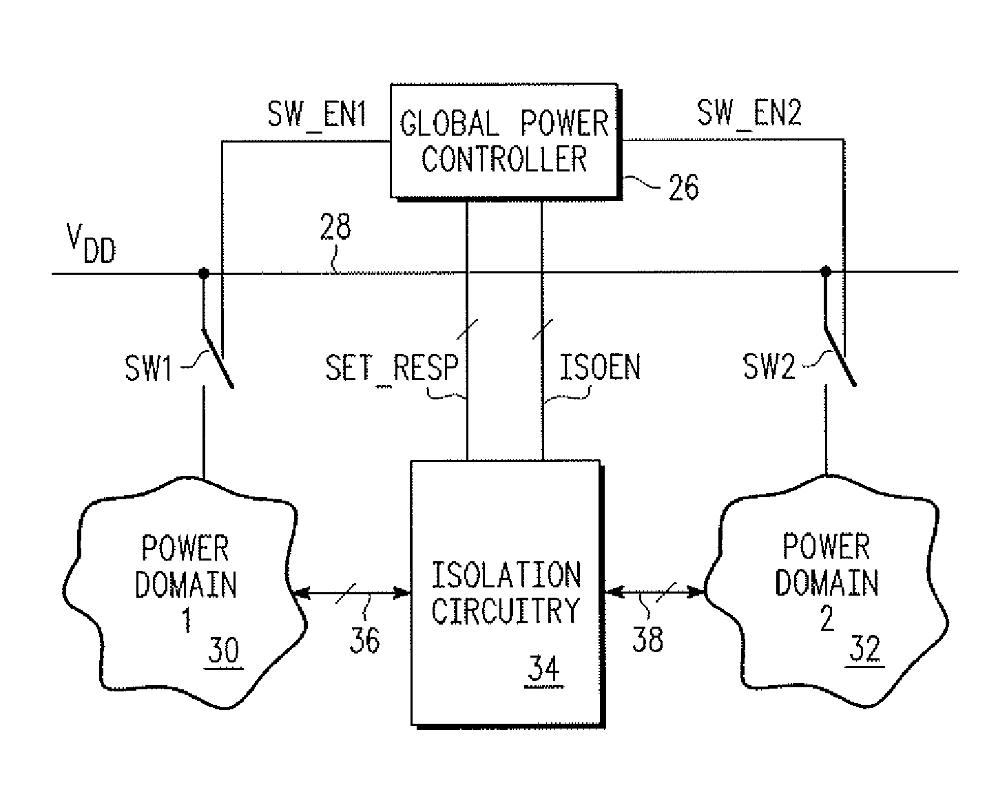
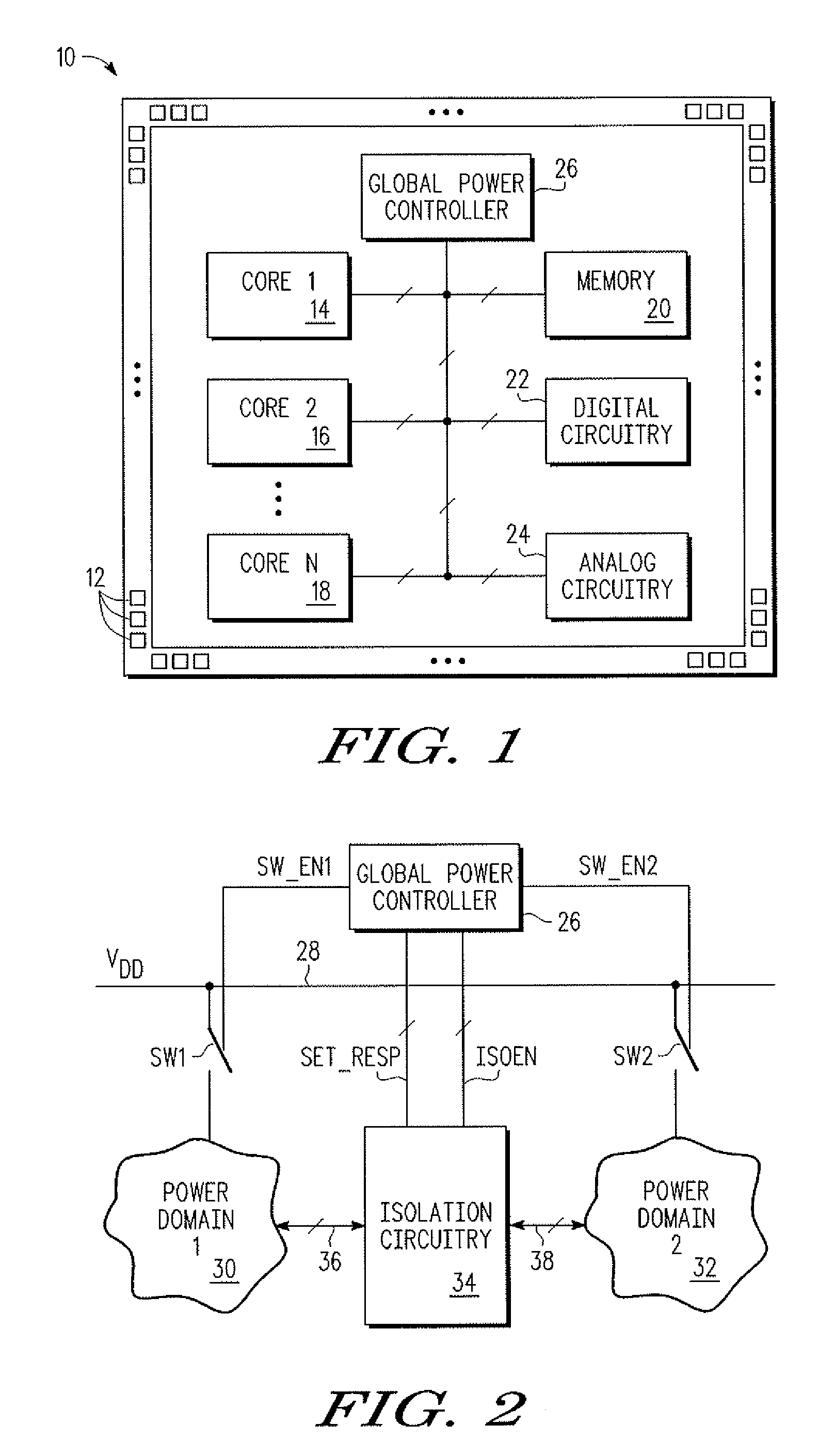
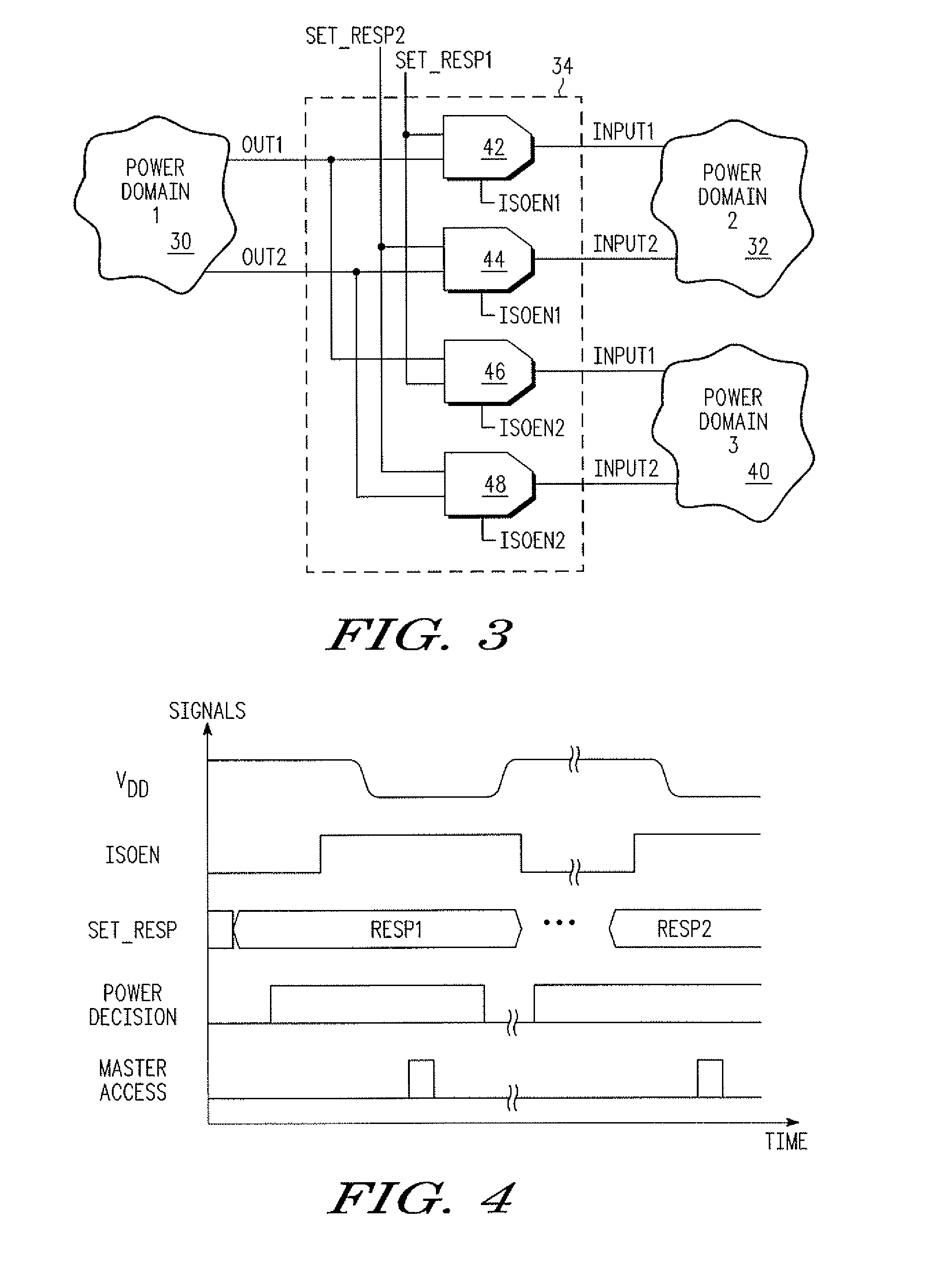
[0014]In one aspect, a circuit including a first power domain, the first power domain including a first set at least one terminal, the first set of at least one terminal configured for providing signals, is provided. The circuit further includes a second power domain, the second power domain including a second set of at least one terminal, the second set configured for receiving signals, the first power domain is power gatable with respect to the second power domain. The circuit further includes a controller circuit, the controller circuit having a third set of at least one terminal for providing programmable values. The circuit further includes isolation circuitry having an input coupled to the first set of at least one terminal, a second input coupled to the third set of at least one terminal, and an output coupled to the second set of at least one terminal, the isolation circuitry including an input to receive an isolate signal, wherein the isolation circuit couples the first set...


PUM


Abstract

A method of operating a circuit, including operating in a first mode, wherein in the first mode, a first power domain operates in an active power mode and a second power domain operates in an active power mode, wherein in the first mode, a first set of at least one terminal of a first circuit of the first power domain are coupled to a second set of at least one terminal of a second circuit of the second power mode via an isolation circuit for providing signals from the first circuit to the second circuit, is provided. The method further includes operating the circuit in a second mode, wherein in the second mode, the first power domain operates in a power gated mode and a second power domain operates in an active power mode.

Description

BACKGROUND[0001]1. Field[0002]This disclosure relates generally to power management, and more specifically, to systems and methods for power management related to power domains in an integrated circuit device.[0003]2. Related Art[0004]To manage power consumption by devices, such as processors, various modules may be in an active mode or in a standby mode. For example, in a wireless baseband processor, certain modules of the baseband processor may be in an active mode while certain other modules may be in standby mode. Moreover, among the modules that are in standby mode, a subset of the modules may be always alive whereas another subset may be power gated. The subset of the modules that are always alive are referred to as being in the alive domain and the subset of the modules that are power gated are referred to as being in the power gated domain.[0005]Typically, isolation cells are used to isolate the alive domain from the power gated domain. Moreover, when the modules in a power ...

Claims


Application Information

Patent Timeline
IPC IPC(8): G06F1/32
CPCY02B60/1282G06F1/3287G06F1/3203Y02B60/1278Y02D10/00
Inventor PADHYE, MILIND P.BAMFORD, NOAH W.SINGHANIA, ANUJ
Owner NXP USA INC
Why Eureka
Try Eureka