
Orbital welding system and methods of operations

a welding system and orbital welding technology, applied in the field of orbital welding system and methods of operation, can solve the problems of tack welding, by itself, not addressing the problem of creating acceptable alignment, and the problem of misalignment of orbital welding, etc., to achieve greater system reliability and safety, and the effect of greater duty cycle in manufacturing and maintenance settings

Inactive Publication Date: 2010-03-04
ARC MACHINES
View PDF73 Cites 24 Cited by
  • Summary
  • Abstract
  • Description
  • Claims
  • Application Information

AI Technical Summary

Benefits of technology

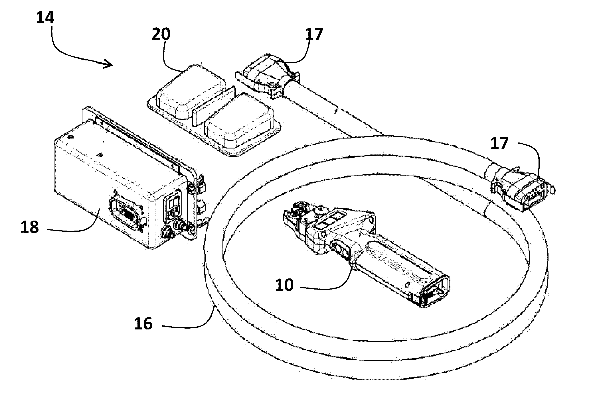
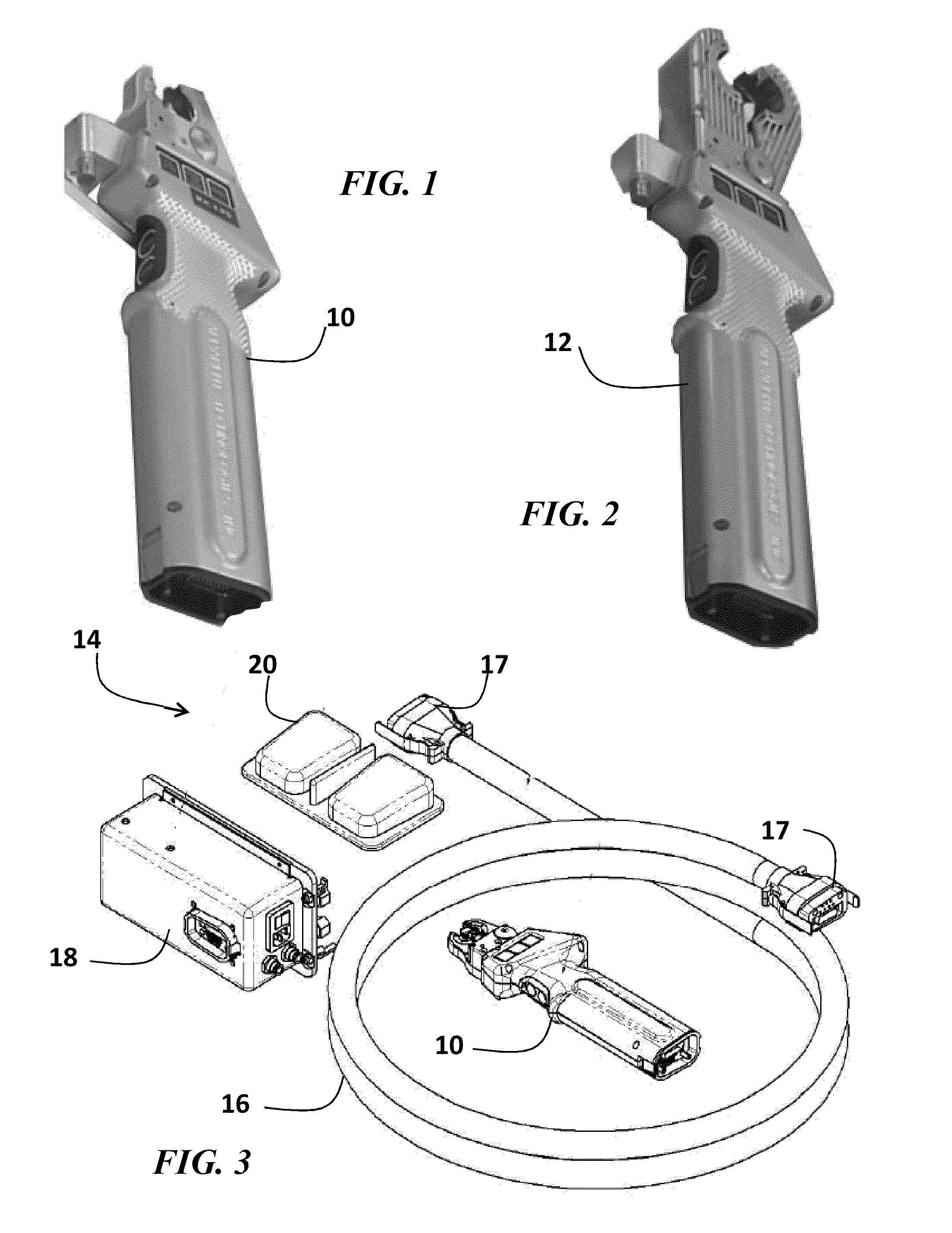
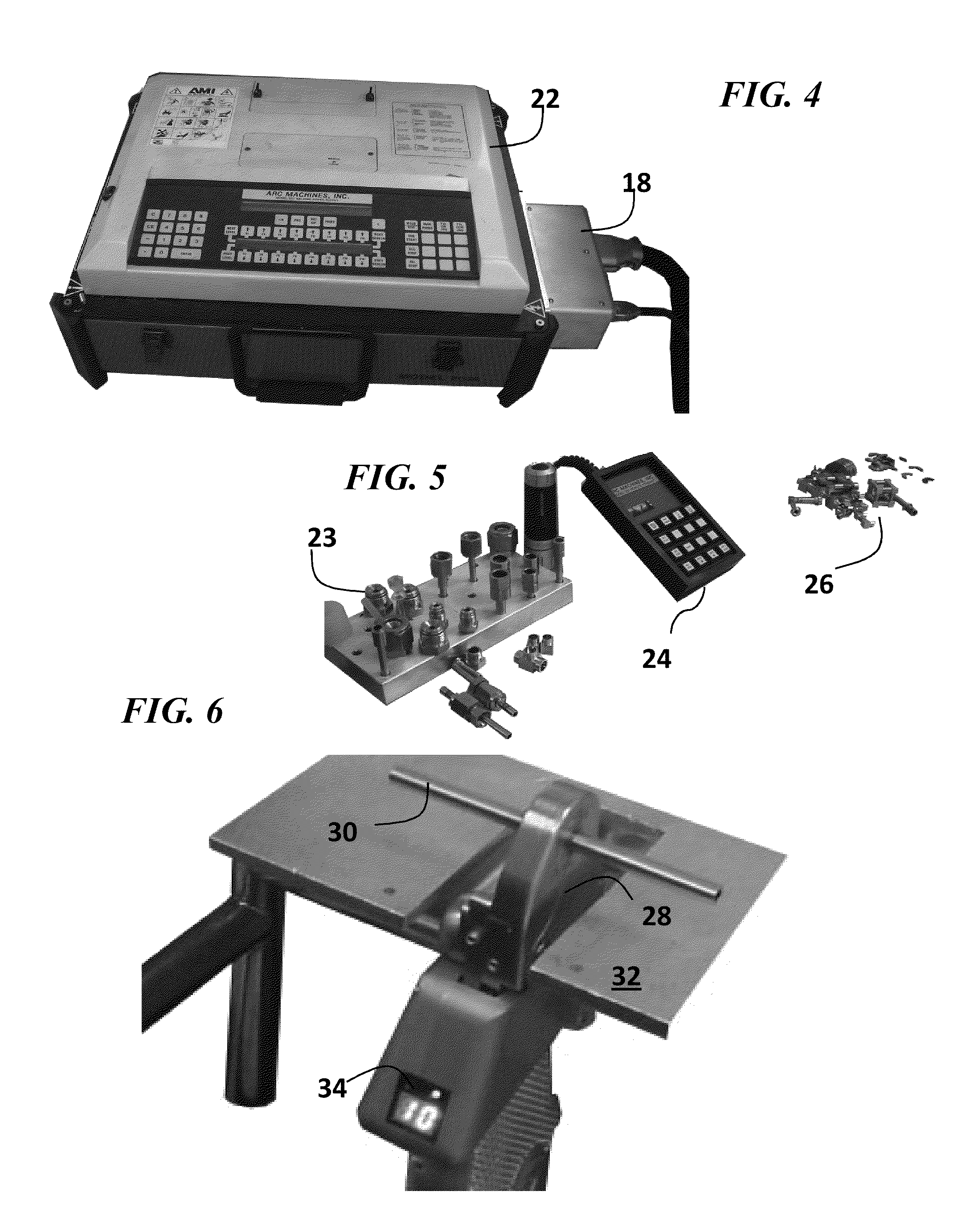
The present patent describes an orbital welding system and methods for safely and controllably welding two tubular materials together. The system includes a weld head with interlocking clamps for sequentially clamping the materials, an alignment mechanism for aligning them, and a weld environment mechanism for creating a gaseous environment for welding. The system orbits the materials in an orbital welding process. The patent also includes a weld head interface circuitry for controlling operational and safety parameters. The technical effects of this system include improved efficiency, accuracy, and safety in welding tubular materials.

Problems solved by technology

Orbital welding however does not solve the problem of misalignment.
Also, orbital welding may be used where a tube or pipe to be welded cannot be rotated or readily rotated, or where space restrictions limit the physical size of the orbital welding equipment.
But, when using tack welding, proper alignment is critical, and therefore, tack welding, by itself, does not address the problem of creating acceptable alignment in a time efficient manner.

Method used


Image

  • Orbital welding system and methods of operations
  • Orbital welding system and methods of operations
  • Orbital welding system and methods of operations

Examples


Embodiment Construction

[0047]In the present specification, an embodiment showing a singular component should not be considered limiting. Rather, the subject matter encompasses other embodiments including a plurality of the same component, and vice-versa, unless explicitly stated otherwise herein. Moreover, applicants do not intend for any term in the specification or claims to be ascribed an uncommon or special meaning unless explicitly set forth as such. Further, the present subject matter encompasses present and future known equivalents to the known components referred to herein by way of illustration.

[0048]More information regarding the field of this invention appears in the following patents, all of which have common assignment and inventorship: U.S. Pat. No. 5,679,271, entitled “Apparatus and method for precisely aligning and tack welding two pieces of weldable material”; U.S. Pat. No. 6,121,567, entitled “Apparatus and method for precisely aligning and welding two pieces of weldable material”; U.S. ...


PUM

PropertyMeasurementUnit
distanceaaaaaaaaaa
weldableaaaaaaaaaa
physical relative alignmentaaaaaaaaaa

Abstract

An orbital welding system and methods of operation controllably and safely weld a first metal tubing to a second metal tubing. A weld head includes interlocking clamping jaws for clamping the tubing. An alignment mechanism aligns the second tubing with the first tubing. The interlocking clamping jaws clamp the second tubing following the aligning of the second tubing with the first tubing. An alignment measurement mechanism measures relative alignment between the first tubing and the second tubing. A weld environment mechanism establishes a gaseous environment for orbitally welding the first tubing to the second tubing. The weld environment mechanism includes a weld environment sealing mechanism for sealing the gaseous environment and an electrode for gas arc welding. The weld environment mechanism orbits the first tubing and second tubing during the orbitally welding. Interface circuitry interfaces a power supply with the weld head and controls parameters associated with said weld head.

Description

CROSS REFERENCE TO RELATED APPLICATIONS[0001]This U.S. patent application claims the benefit of priority of U.S. Provisional Patent Application No. 61 / 050,858 filed May 6, 2008 entitled, “Orbital Weld Head System,” by inventor Michael Guerrina.FIELD[0002]The present subject matter relates generally to orbital welding system and methods of operations, and more particularly, to a system and method for an orbital weld head system with automated clamping and alignment measurement.DESCRIPTION OF THE RELATED ART[0003]An orbital welding system consists of a solid-state power supply (operating from 110 VAC) and a rotor and electrode housed in the orbital weld head. The power supply and microprocessor technology system supplies and controls the system's output characteristics, i.e., welding parameters, like the arc welding current, the power to drive the motor in the weld head, and the switching on and off of the shield gas, are programmed.[0004]In automatic orbital welding systems, a clampi...

Claims


Application Information

Patent Timeline
Patent Type & Authority Applications(United States)
IPC IPC(8): B23K11/00
CPCB23K9/0286
Inventor GUERRINA, MICHAELJOBE, CARLOS
Owner ARC MACHINES
Learn More