
Face Panel for a Computer Housing

a computer housing and face panel technology, applied in the direction of mechanical equipment, furniture parts, instruments, etc., can solve the problems of inability to re-assemble the cover, inconvenient for users, and inability to remove the cover from the front side of the face, so as to achieve quick and convenient removal

Inactive Publication Date: 2010-03-04
AOPEN
View PDF34 Cites 12 Cited by
  • Summary
  • Abstract
  • Description
  • Claims
  • Application Information

AI Technical Summary

Benefits of technology

[0008]Therefore, the main object of the present invention is to provide a face panel for a computer housing, which has a cover plate assembly that can be assembled to or disassembled from a face panel body in a quick and convenient manner.
[0015]In the aforementioned face panel for a computer housing, the cover plate may be configured to have one or two guide grooves. If the cover plate is configured to have two guide grooves, the guide grooves are provided in the rear face of the cover plate, extend in the left-right direction, and are respectively proximate to upper and lower ends of the cover plate. The locking member may be connected slidably between the two guide grooves. The guide groove includes a first end, and a second end opposite to the first end. The locking member has first and second protrusions located within the guide groove for abutting against the first end and for abutting against the second end, respectively. The restoring resilient plate applies the pressure to the cover plate such that the first protrusion abuts against the first end, thereby limiting a distance of movement of the locking member.
[0016]In the aforementioned face panel for a computer housing, the locking member has an elongated guide hole extending along the left-right direction. The elongated guide hole includes a first end portion, and a second end portion opposite to the first end portion. The cover plate further has first and second studs located within the elongated guide hole. The first and second studs are disposed for abutting against the first and second end portions, respectively. The restoring resilient plate applies the pressure to the cover plate such that the first stud abuts against the first end portion, thereby limiting the distance of movement of the locking member.
[0018]In the face panel for a computer housing according to the present invention, with the arrangement of the cover plate assembly, rotation of the unlocking member by the user can drive the locking member to move so that the second engaging hook of the locking member is disengaged from the second engaging groove, thereby permitting quick and convenient removal of the cover plate assembly from a front side of the face panel body. In addition, with the use of the restoring resilient plate to restore the second engaging hook to an engaging position, the cover plate assembly and the face panel body may be switched between locked and unlocked states.

Problems solved by technology

The removal operation cannot be conducted from a front side of the face panel body 11, which is inconvenient for the user during removal.
Furthermore, if a force is improperly applied by the user during removal of the covers 12, breaking of the engaging hooks 122 may occur, thereby rendering it impossible to re-assemble the covers 12 to the face panel body 11.

Method used


Image

  • Face Panel for a Computer Housing
  • Face Panel for a Computer Housing
  • Face Panel for a Computer Housing

Examples


Embodiment Construction

[0034]Through a detailed description of the preferred embodiments, the technical means adopted to achieve the intended object and advantageous effects of the present invention should be better understood. However, the accompanying drawings are provided for reference and illustration only and should not be based upon to limit the scope of protection sought for the present invention.

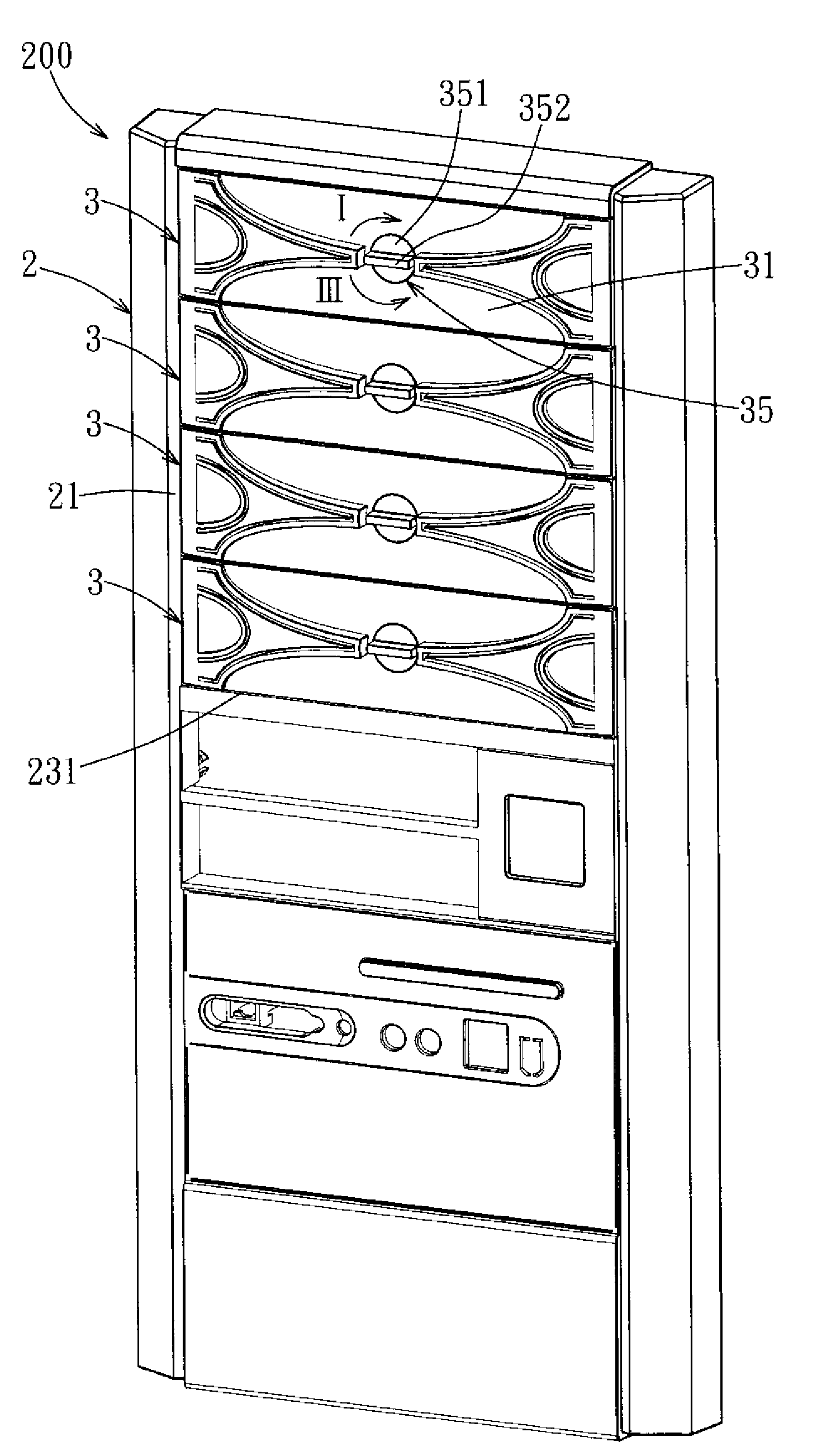
[0035]Before the present invention is described in greater detail, it should be noted that like elements are denoted by the same reference numerals throughout the disclosure.

[0036]Referring to FIG. 4, the first preferred embodiment of a face panel 200 for a computer housing according to the present invention is shown to include a face panel body 2 and a plurality of cover plate assemblies 3 removably assembled to the face panel body 2. Since the cover plate assemblies 3 are identical in structure, to facilitate description and for the sake of clarify, the cover plate assemblies 3, and component parts there...


PUM


Abstract

A face panel for a computer housing includes a face panel body and a cover plate assembly. The face panel body includes a surrounding wall and a mounting hole. The surrounding wall has first and second engaging grooves. The cover plate assembly includes a cover plate, a locking member, and an unlocking member. The cover plate has a first engaging hook for engaging the first engaging groove, and a guide groove. The locking member is assembled to the guide groove, and has a second engaging hook, a post, and a restoring resilient plate to apply a pressure to the cover plate so as to enable the second engaging hook to engage the second engaging groove. The unlocking member has an operating portion, and a contact portion movable with the operating portion so as to push the post for disengaging the second engaging hook from the second engaging groove.

Description

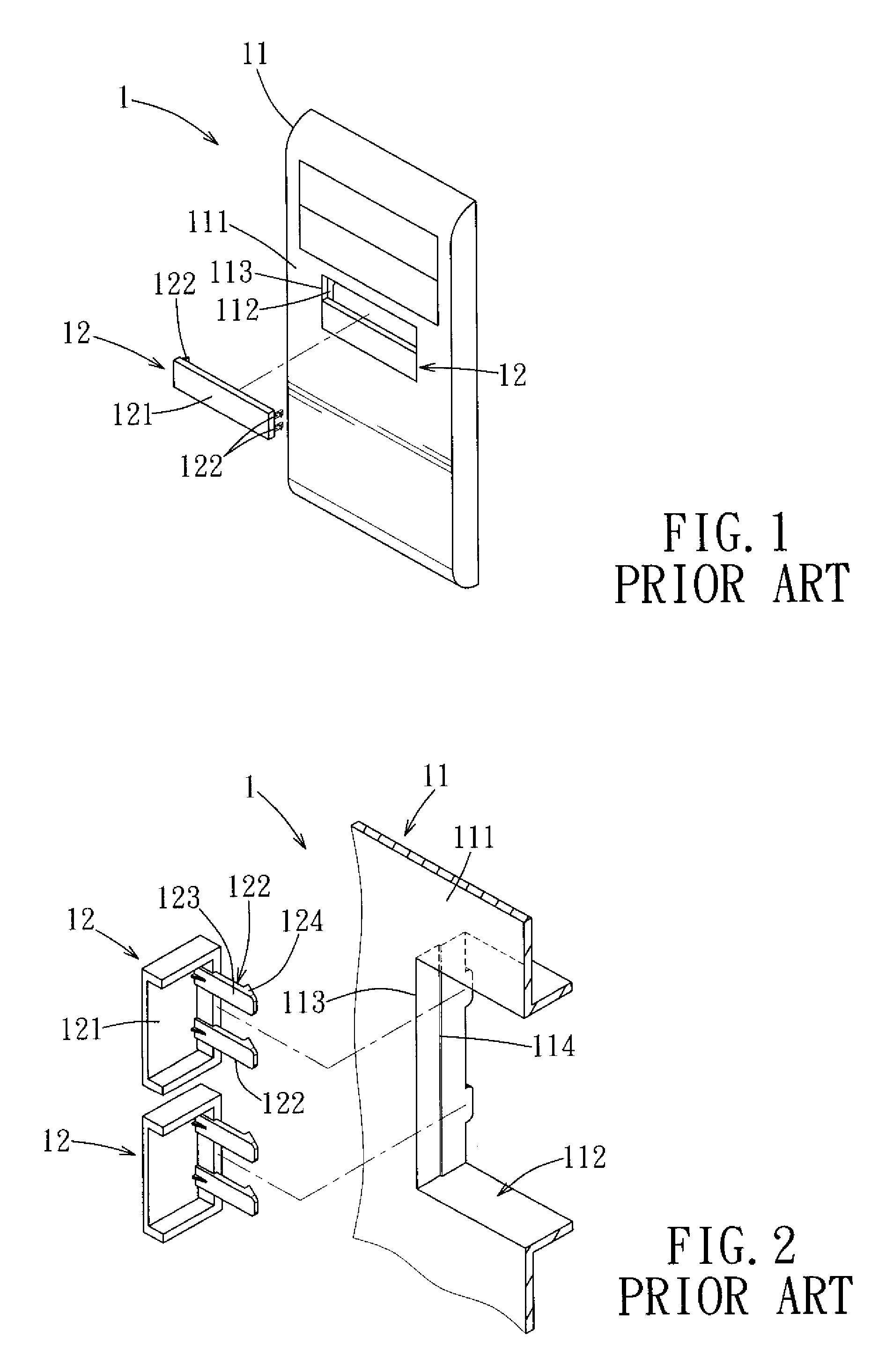
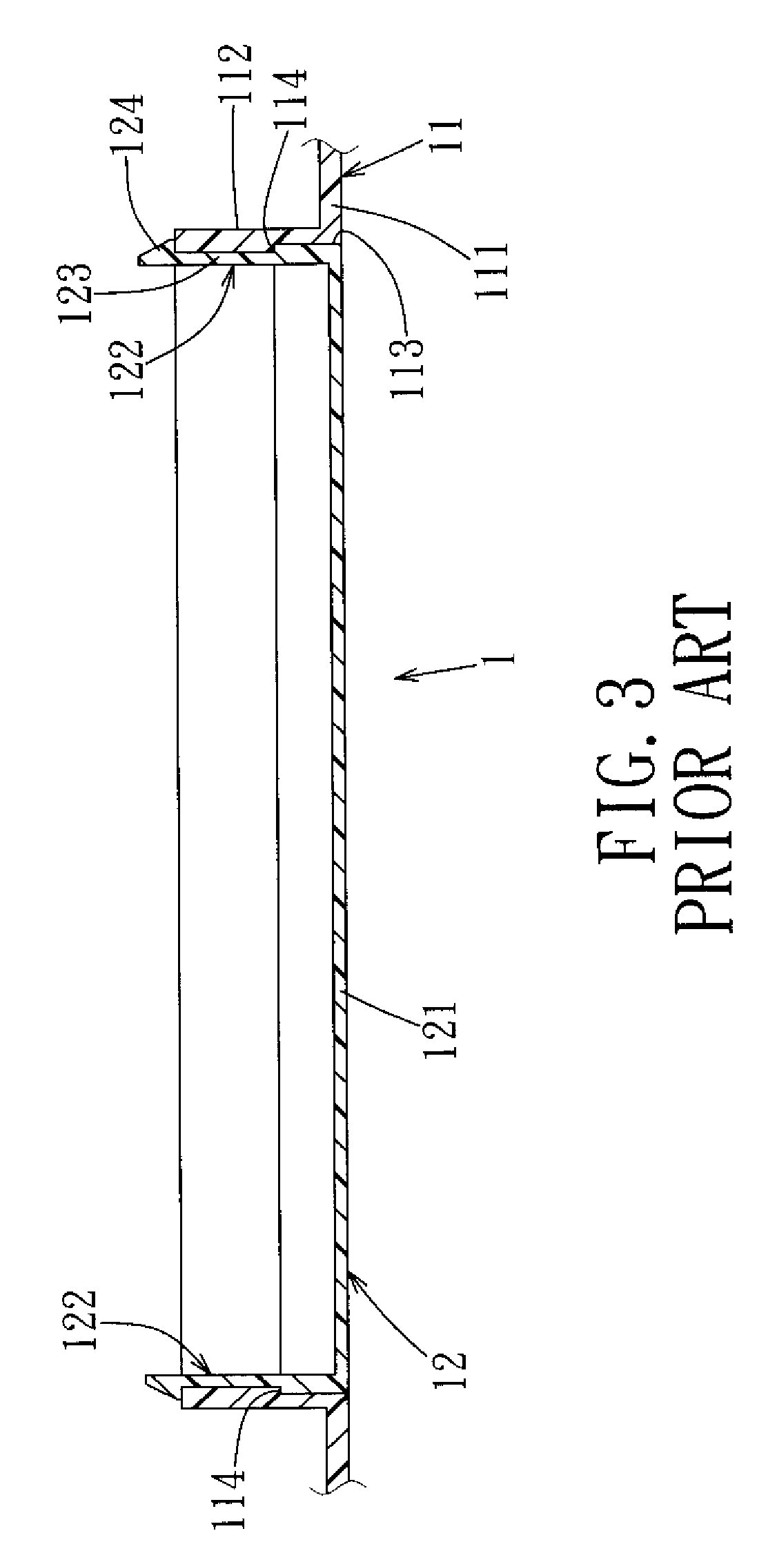
CROSS-REFERENCE TO RELATED APPLICATION[0001]This application claims priority of Taiwanese Application No. 09721531, filed on Aug. 26, 2008.BACKGROUND OF THE INVENTION[0002]1. Field of the Invention[0003]The invention relates to a face panel for a computer housing, more particularly to a face panel for a computer housing which has a mounting hole for insertion of a data access device and which permits a cover plate assembly to be mounted in the mounting hole.[0004]2. Description of the Related Art[0005]Referring to FIGS. 1, 2, and 3, a face panel 1 of a conventional computer housing includes a face panel body 11, and a plurality of covers 12 removably assembled to the face panel body 11. The face panel body 11 includes an upright wall 111, a mounting hole 113 formed in the upright wall 111, and a surrounding wall 112 projecting rearwardly from the upright wall 111 and defining the mounting hole 113. The surrounding wall 112 is for mounting of data access devices, such as an optical d...

Claims


Application Information

Patent Timeline
IPC IPC(8): A47B81/00
CPCG06F1/187G06F1/181Y10T292/0897Y10T292/0898Y10T292/096Y10T292/1023
Inventor WANG, JO-CHIAOWEN, HSUAN-YING
Owner AOPEN
Learn More