Electronic apparatus

Inactive Publication Date: 2010-03-04
PANASONIC CORP
View PDF7 Cites 12 Cited by
  • Summary
  • Abstract
  • Description
  • Claims
  • Application Information

AI Technical Summary

Benefits of technology

[0011]Furthermore, since the application of heat to the rechargeable cell due to the start-up of the electronic apparatus can b

Problems solved by technology

Consequently, a portion of the power from the AC adapter is consumed by the apparatus main body, and the charging efficiency is reduced.
Furthermore, the start-up of the apparatus main body heats the battery, thereby promoting a temperature rise in the

Method used


Image

  • Electronic apparatus
  • Electronic apparatus
  • Electronic apparatus

Examples


Example

[0016]Below, an embodiment of the present invention will be described with reference to the drawings.

1. Composition

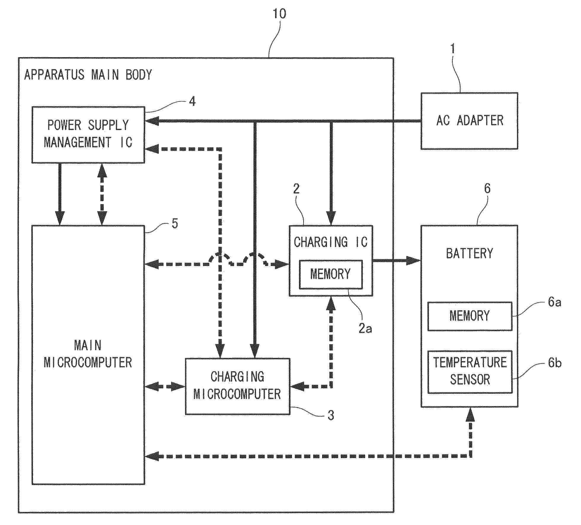
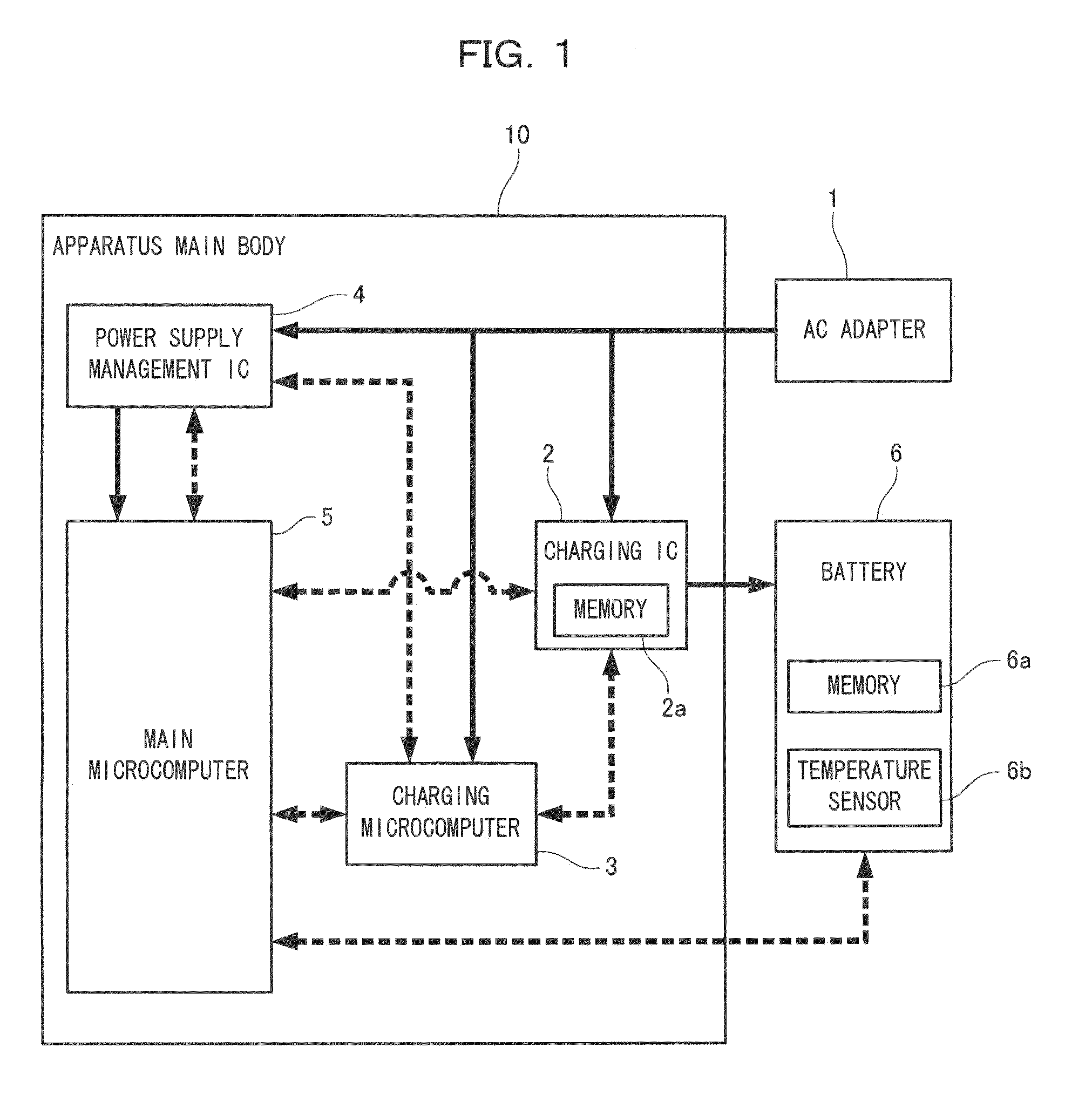
[0017]FIG. 1 is a block diagram showing the composition of a video camera which is an electronic apparatus relating to the embodiment of the present invention. In FIG. 1, an AC adapter 1 is attachable to and detachable from an apparatus main body 10 (a connected state is shown in FIG. 1) and supplies power to a video camera. A charging IC 2 charges a rechargeable battery 6 serving as a rechargeable cell (hereinafter called “battery 6”). A charging microcomputer 3 controls the on / off switching of the charging operation. A power supply management IC 4 controls the on / off of the operation of a main microcomputer 5. The main microcomputer 5 serving as the main controller controls the apparatus main body 10, which is the electronic apparatus. The battery 6 supplies power to the apparatus main body 10 by being connected to (installed in) the apparatus main body 10, and can be...


PUM


Abstract

During charging of a battery, the start-up of the main body of an apparatus due to the switching on of a controller leads to increased consumption of power and also leads to heating of the battery, and therefore it is not possible to pass a sufficient charging current. A main microcomputer 5 serving as a main control apparatus, a charging IC 2 that performs charging of a battery 6, and a charging microcomputer 3 are provided. The charging microcomputer 3 monitors the operation of the main microcomputer 5, and the charging microcomputer 3 prohibits the charging operation by the charging IC 2 if the main microcomputer 5 is operating, and permits the charging operation by the charging IC 2 if the main microcomputer 5 is not operating.

Description

BACKGROUND OF THE INVENTION[0001]1. Field of the Invention[0002]The present invention relates to an electronic apparatus, such as a video camera, which uses a rechargeable cell.[0003]2. Description of the Related Art[0004]A rechargeable battery (rechargeable cell), such as a lithium ion (Li-ion) or a nickel hydrogen (Ni—H) battery, is used in the power supply of a portable electronic apparatus such as a mobile phone, a portable CD player and a digital still camera (DSC). In a conventional electronic apparatus of this kind, a main microcomputer, which controls the system of the apparatus main body, controls charging of power from an AC adapter to a rechargeable battery (hereinafter, called “battery”) via the apparatus main body. Japanese Patent Application Laid-Open Publication No. 2007-025260 relates to this technique.[0005]Conventionally, in the electronic apparatus of this kind, the apparatus main body is started up due to the start-up of the main microcomputer, even during chargi...

Claims


Application Information

Patent Timeline
IPC IPC(8): H02J7/00G06F1/26H02J7/02
CPCH02J7/0068
Inventor OTA, YUSUKEIWAI, TOSHIOTAKEMORI, YOSHIHARU
Owner PANASONIC CORP
Why Eureka
Try Eureka