Inverter control device

a technology of inverter control and control device, which is applied in the direction of electric commutators, propulsion by batteries/cells, transportation and packaging, etc., can solve the problems of large current reflux and significant rise in voltage across the terminals of dc link capacitors, so as to suppress a rise in voltage, and suppress a large current

Active Publication Date: 2017-03-30
AISIN AW CO LTD
View PDF2 Cites 11 Cited by
  • Summary
  • Abstract
  • Description
  • Claims
  • Application Information

AI Technical Summary

Benefits of technology

[0006]In light of the aforementioned circumstances, there is desire for technology for, in the case where a contactor that connects an inverter and a DC power supply has entered the open state, suppressing a rise in the DC link voltage of the inverter and suppressing the total amount of reflux current, while also setting the amount of current flowing in the rotating electric machine to zero.
[0008]According to this configuration, after the contactor has entered the open state, mixed loop control is executed so as to form one capacitor charging loop and one reflux loop. In other words, mixed loop control is executed such that shutdown control for forming a capacitor charging loop and active short control for forming a reflux loop are performed at the same time. There is an issue in that although reflux current can be suppressed in shutdown control, the voltage across the terminals of the DC link capacitor (DC link voltage) rises significantly, and although a rise in the DC link voltage can be suppressed in active short control, large current reflux continues to occur. However, if shutdown control and active short control are executed concurrently as in this configuration, it is possible to suppress a rise in voltage caused by shutdown control and suppress a large current generated by active short control. In this way, according to this configuration, in the case where the contactor that connects the inverter and the DC power supply has entered the open state, it is possible to suppress a rise in the DC link voltage of the inverter and suppress the total amount of reflux current, while also setting the current flowing in the rotating electric machine to zero even in the state where the rotational speed of the rotating electric machine is not zero.

Problems solved by technology

There is an issue in that although reflux current can be suppressed in shutdown control, the voltage across the terminals of the DC link capacitor (DC link voltage) rises significantly, and although a rise in the DC link voltage can be suppressed in active short control, large current reflux continues to occur.

Method used


Image

  • Inverter control device
  • Inverter control device
  • Inverter control device

Examples


Embodiment Construction

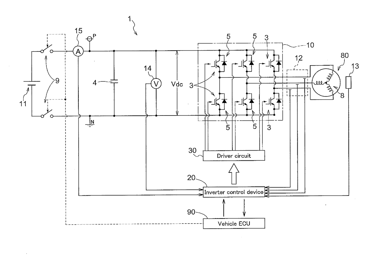
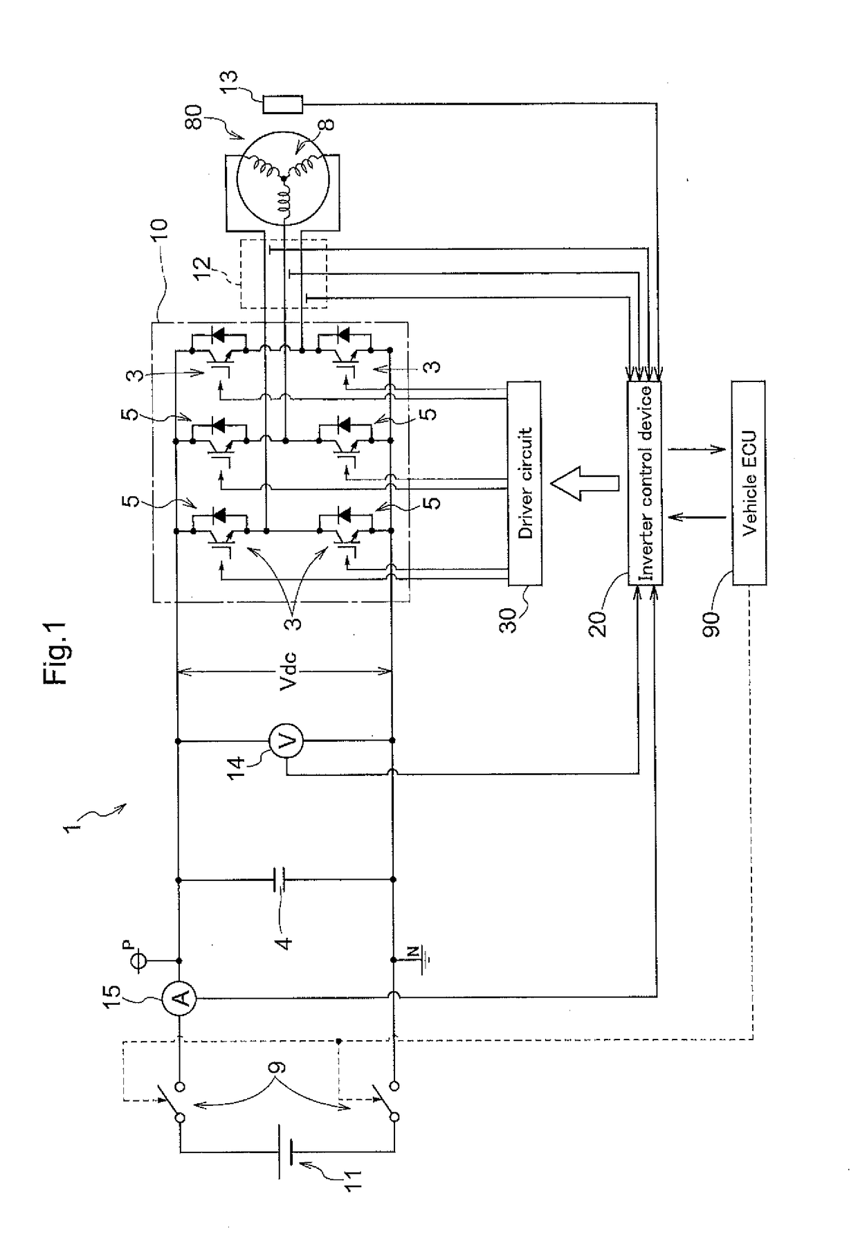
[0020]Hereinafter, an embodiment of an inverter control device will be described based on the drawings. As shown in FIG. 1, an inverter control device 20 is for controlling a rotating electric machine drive device 1 that includes an inverter 10 and a DC link capacitor 4, and controls driving of a rotating electric machine 80 via the rotating electric machine drive device 1. As will be described later, the inverter 10 is a power conversion device that is connected to a DC power supply (11) via a contactor 9, is connected to the AC rotating electric machine 80, and performs power conversion between direct current and polyphase alternating current (here, three-phase alternating current), and an arm for each alternating current phase is constituted by a series circuit including an upper side switching element and a lower side switching element. The DC link capacitor 4 smooths a DC link voltage Vdc, which is the DC-side voltage of the inverter 10. The rotating electric machine 80, which ...


PUM


Abstract

An inverter control device for controlling a rotating electric machine drive device that drives an alternating current rotating electric machine and includes an inverter and a DC link capacitor, the inverter being connected to a DC power supply via a contactor, being connected to the rotating electric machine, and performing power conversion between direct current and three-phase alternating current, the DC link capacitor smoothing a DC link voltage, which is a DC-side voltage of the inverter, and the inverter control device performing switching control on switching elements that form the inverter.

Description

BACKGROUND[0001]The present disclosure relates to technology for controlling driving of an alternating current rotating electric machine.[0002]A high-output alternating current (AC) rotating electric machine used to power an electric automobile, a hybrid automobile, or the like is driven with a high voltage. Since the high-voltage power supply installed in such an automobile is a DC battery, DC power is converted into three-phase alternating current, for example, by an inverter circuit that uses switching elements. The rotating electric machine not only functions as a motor that outputs power for driving the vehicle using electrical energy, but also functions as a generator that generates electricity using kinetic energy from the vehicle, an internal combustion engine, or the like. Electrical power generated by the rotating electric machine is regenerated and stored in a battery.[0003]Incidentally, there are cases where a switchgear (contactor) is provided between the battery and th...

Claims


Application Information

Patent Timeline
Patent Type & Authority Applications(United States)
IPC IPC(8): H02P29/024H02M1/36B60L11/18H02P27/08H02P6/14
CPCH02P29/024H02P27/08H02M1/36B60L11/1803H02P6/14B60L50/51H02M7/5387H02M7/797H02P9/006H02P29/0243H02P29/032H02P29/0241H02M1/322Y02T10/70
Inventor SAHA, SUBRATASHIMADA, ARINORI
Owner AISIN AW CO LTD
Why Eureka
Try Eureka