Subcutaneous infusion device

a technology of infusion device and subcutaneous injection, which is applied in the direction of medical devices, infusion needles, other medical devices, etc., can solve the problems of reducing the convenience of patient life, requiring delicate operations, and reducing sensation, so as to achieve the effect of easy detachment/attachment of coupling parts

Inactive Publication Date: 2010-03-04
NIPRO CORP
View PDF13 Cites 13 Cited by
  • Summary
  • Abstract
  • Description
  • Claims
  • Application Information

AI Technical Summary

Benefits of technology

[0018]An object of the present invention is to provide a subcutaneous infusion device that enables easy detachment / attachment of a coupling member from / to an indwelling member.

Problems solved by technology

However, in the daily life of a patient (e.g. bathing, exercising, and the like), a fluid infusion line of the subcutaneous infusion device becomes obstructive and tends to decrease convenience in the patient's life.
To operate the two mechanisms described above, a delicate operation is generally required.
However, some of the patients who undergo treatment of continuous subcutaneous insulin infusion have peripheral neuropathy and others, and hence suffer from diminished sensation in the fingers, find difficulties in performing a delicate operation, and tend to find it difficult to smoothly manipulate the coupling mechanism and the separating mechanism.
As such, the subcutaneous infusion device according to Patent Document 1 requires a delicate operation in manipulating the coupling and separating mechanisms.
However, when the indwelling member is actually secured on the skin, it is often secured at a section that is difficult to check by visual inspection (the lower abdomen, the buttocks, or the like), so that in actual use, it is difficult to insert the coupling member into the hinge portion.
However, a “separating” manipulation is still difficult to perform.
Further, in the subcutaneous infusion devices described in Patent Documents 4 and 5, a puncture portion of an indwelling member is located at a recessed site, and hence the direction along which the coupling member is attached is limited, resulting in that attachment of the coupling member is sometimes difficult.
Further, in the subcutaneous infusion device described in Patent Document 6, a direction along which the coupling member is attached is limited to a direction running from upward toward a surface of the body, and hence attachment of the coupling member is sometimes difficult.

Method used


Image

  • Subcutaneous infusion device
  • Subcutaneous infusion device
  • Subcutaneous infusion device

Examples


first embodiment

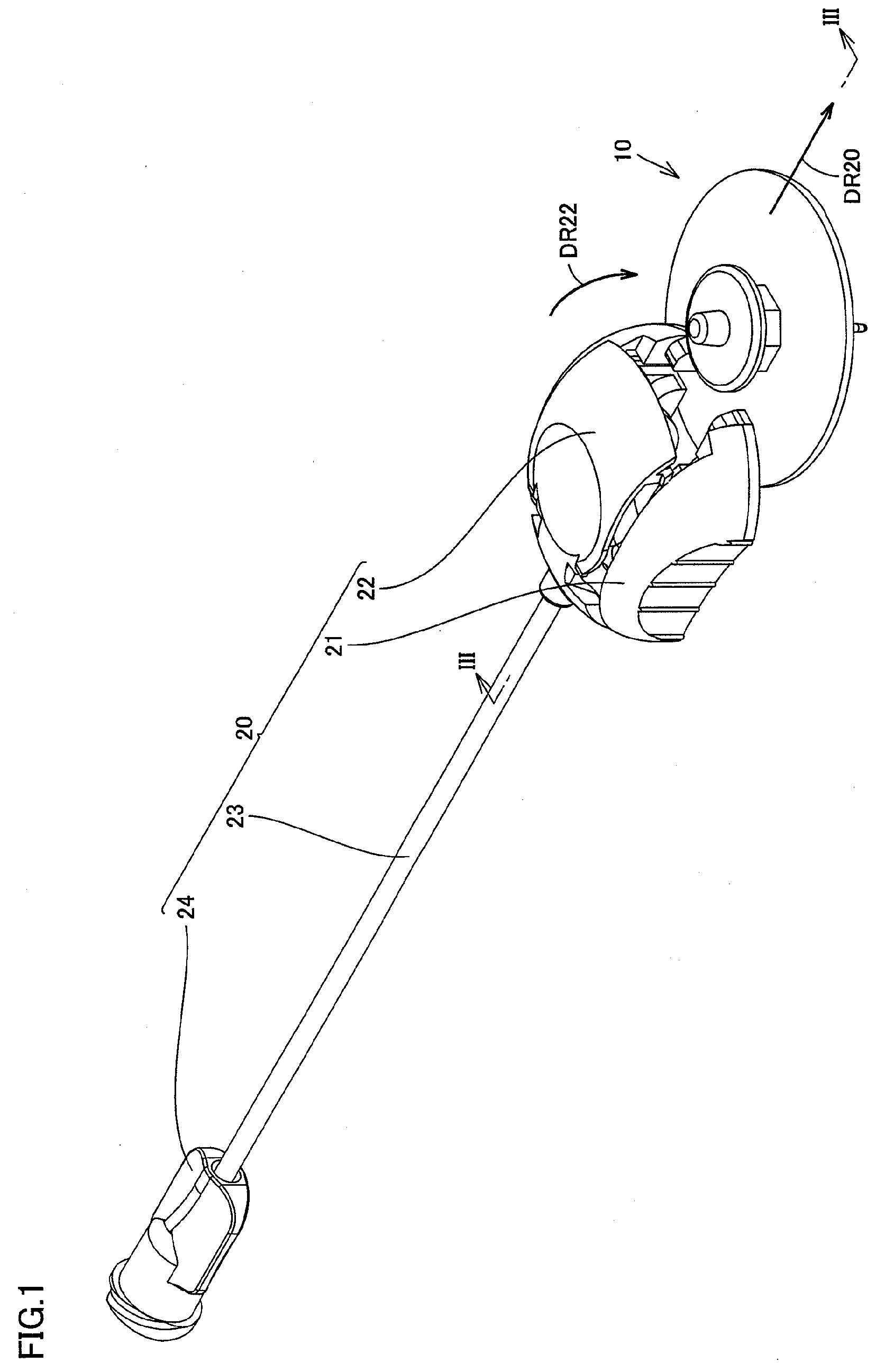
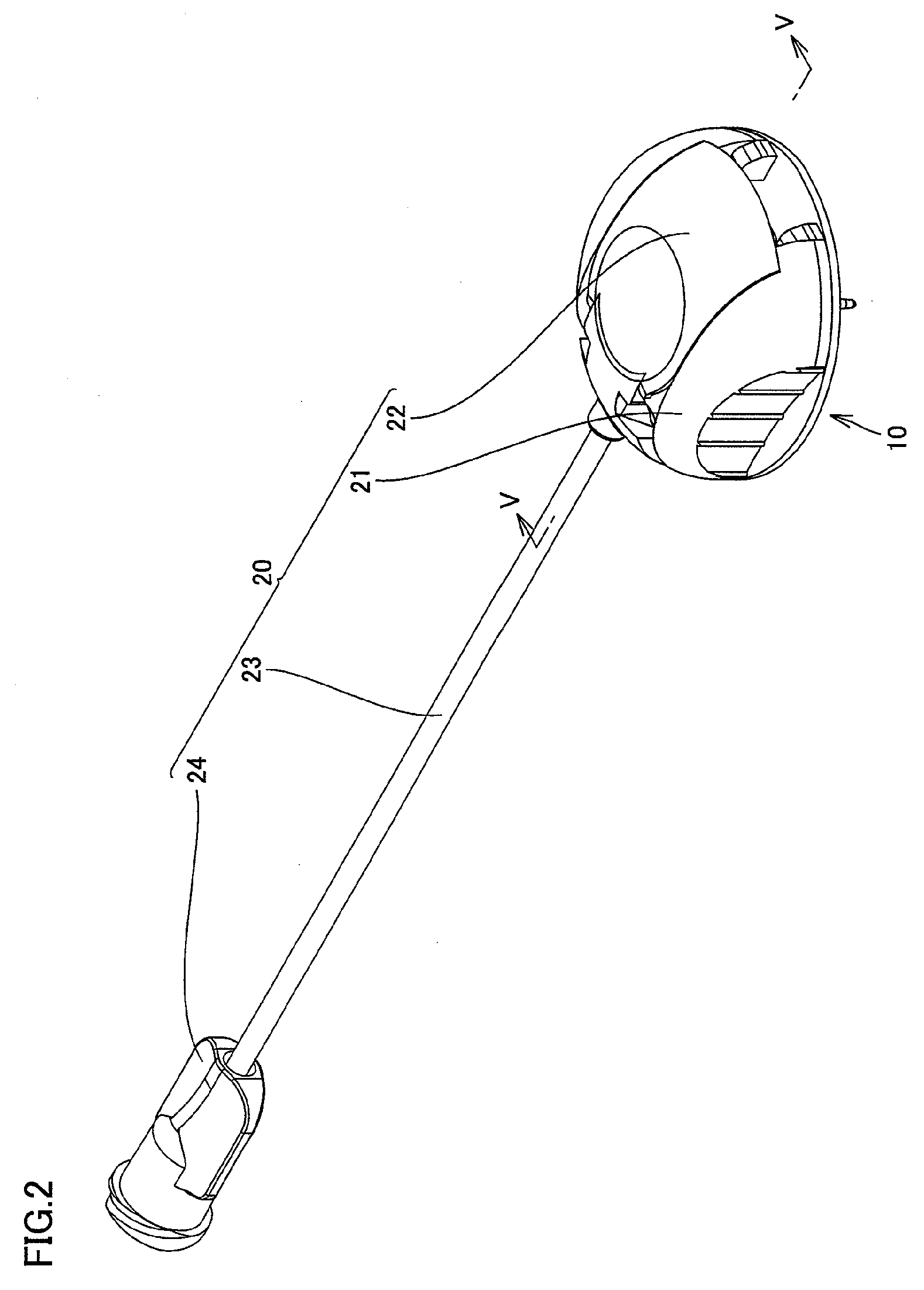
[0081]FIG. 1 is a perspective view that shows a state prior to attachment of a coupling member of a subcutaneous infusion device according to a first embodiment to an indwelling member. FIG. 2 is a perspective view that shows a state where the coupling member of the subcutaneous infusion device is attached to the indwelling member.

[0082]With reference to FIGS. 1 and 2, a subcutaneous infusion device according to the present embodiment is used for continuous subcutaneous insulin infusion (CSII), and configured to include an indwelling member 10 and a coupling member 20. Indwelling member 10 is a member for being secured at a surface of the body of a patient when continuous subcutaneous insulin infusion is carried out. Coupling member 20 is a member for being detached / attached as needed from / to indwelling member 10. In other words, when insulin is subcutaneously infused, coupling member 20 is coupled to indwelling member 10, and when infusion of insulin is suspended (e.g. during bathi...

second embodiment

[0114]FIGS. 14 and 15 are a perspective view that shows a state prior to attachment of coupling member 20 of a subcutaneous infusion device according to a second embodiment of the present invention to indwelling member 10, and a perspective view that shows a state where coupling member 20 is attached to indwelling member 10, respectively. Further, FIGS. 16 and 17 are a drawing that shows a state seen from the direction of an arrow XVI in FIG. 14, and a drawing that shows a state seen from the direction of an arrow XVII in FIG. 15, respectively.

[0115]With reference to FIGS. 14-17, a subcutaneous infusion device according to the present embodiment is a modification of the subcutaneous infusion device according to the first embodiment, characterized in that an elastic member 25A is provided in addition to elastic member 25, as a biasing member in removing coupling member 20. As shown in FIGS. 14-17, elastic member 25A is provided on each of opposite sides of lid portion 22. One end sid...

third embodiment

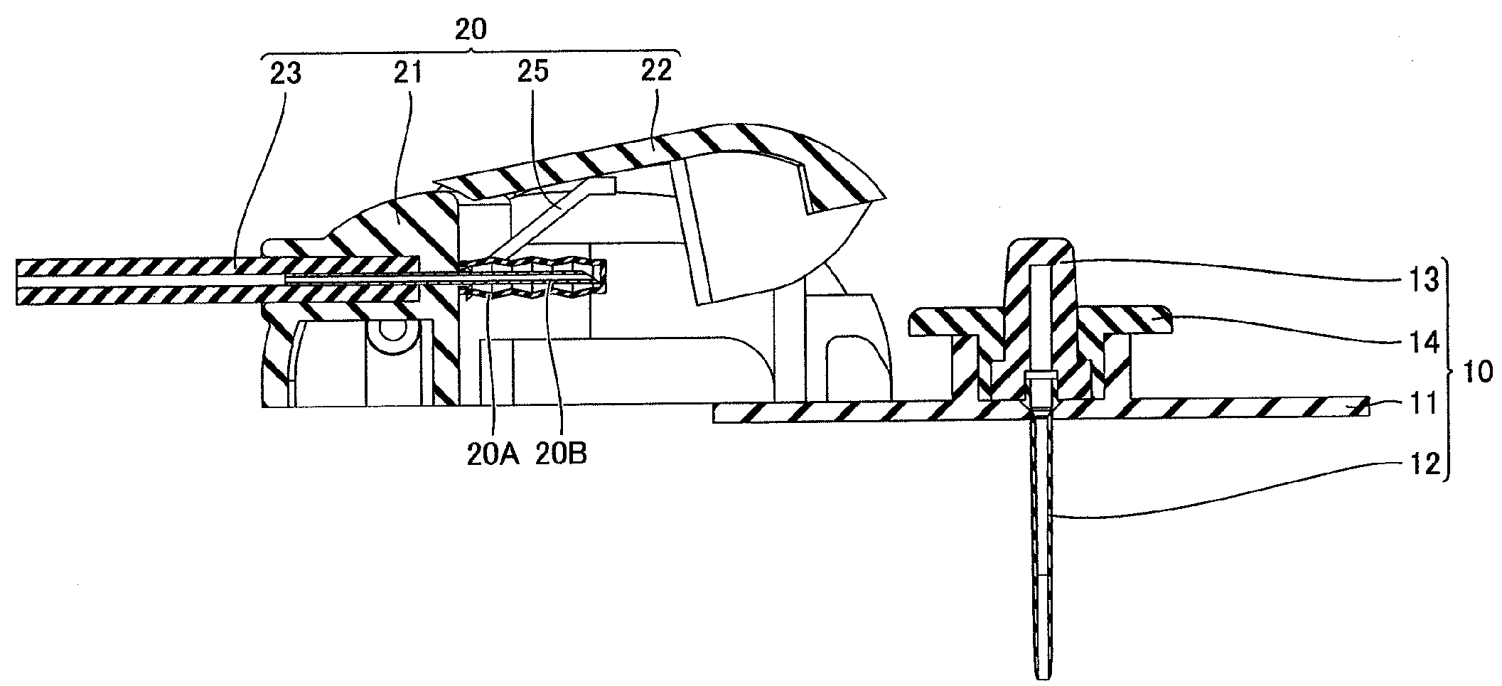
[0116]FIG. 18 is a cross-sectional side view that shows a state where a coupling member of a subcutaneous infusion device according to a third embodiment is attached to an indwelling member. With reference to FIG. 18, a subcutaneous infusion device according to the present embodiment is a modification of the subcutaneous infusion devices according to the first and second embodiments, characterized to have a structure in which needle 20B is inserted through an insertion hole 11B provided at guide portion 11A of indwelling member 10. In other words, in the subcutaneous infusion device according to the present embodiment, guide portion 11A configures a “protruding portion”, and when coupling member 20 is attached to indwelling member 10, needle cover 20A abuts on guide portion 11A and is compressed and deformed.

[0117]In the subcutaneous infusion device according to the present embodiment, locking of lid portion 22 can easily be released as in the first and second embodiments. Further, ...


PUM


Abstract

A subcutaneous infusion device includes an indwelling member which has a base portion and a cannula reaching an inside of a body of a user when the base portion is fixed to a surface of the body of the user, and a coupling member which is attached to the indwelling member in a detachable/attachable manner. The coupling member includes a main body portion, a needle provided at the main body portion and communicated with the cannula when the coupling member is attached to the indwelling member, a lid portion provided turnably with respect to the main body portion, an engagement portion locking the lid portion to the main body portion, and an elastic member biased when the lid portion is locked to the main body portion and capable of biasing the lid portion in a turning direction when the locking is being released.

Description

[0001]This nonprovisional application is based on Japanese Patent Applications Nos. 2008-221962, 2008-221963, and 2008-221964 all filed on Aug. 29, 2008 with the Japan Patent Office, the entire contents of which are hereby incorporated by reference.BACKGROUND OF THE INVENTION[0002]1. Field of the Invention[0003]The present invention relates to a subcutaneous infusion device, and particularly relates to a subcutaneous infusion device for infusing a medical solution into the body of a user.[0004]2. Description of the Background Art[0005]A subcutaneous infusion device used for Continuous Subcutaneous Insulin Infusion (CSII), for example, has been known conventionally. Its specific examples include the ones described in, for example, the specification of U.S. Patent Application Laying-Open No. 2006 / 0129090 (Patent Document 1), the specification of U.S. Patent Application Laying-Open No. 2003 / 0216686 (Patent Document 2), the specification of U.S. Pat. No. 6,056,718 (Patent Document 3), a...

Claims


Application Information

Patent Timeline
Patent Type & Authority Applications(United States)
IPC IPC(8): A61M5/14
CPCA61M2005/1587A61M5/158
Inventor ISHIKURA, KOHZOISHIHARA, NAOKOYAMAGUCHI, TAKESHI
Owner NIPRO CORP
Why Eureka
Try Eureka