Electrical busway flange end stub

a technology of electric busway and flange end, which is applied in the direction of butt joining busway, electric cable installation, coupling device connection, etc., and can solve the problem of increasing the amount of scrap material

Active Publication Date: 2010-03-11
ABB (SCHWEIZ) AG
View PDF11 Cites 11 Cited by
  • Summary
  • Abstract
  • Description
  • Claims
  • Application Information

AI Technical Summary

Problems solved by technology

Unfortunately, the extruded aluminum housing is costly and results in increases the amount of scrap material.

Method used


Image

  • Electrical busway flange end stub
  • Electrical busway flange end stub
  • Electrical busway flange end stub

Examples


Embodiment Construction

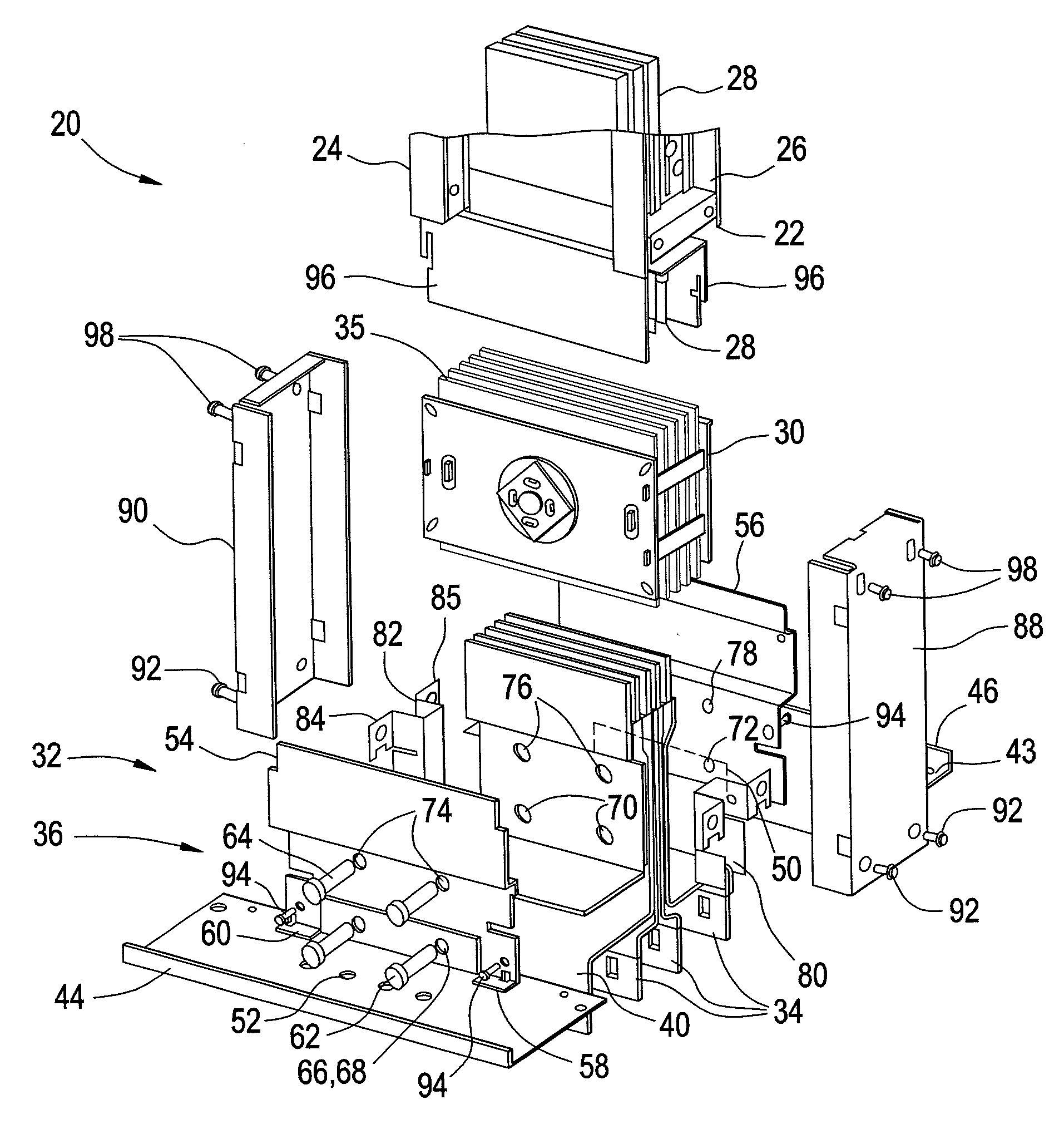
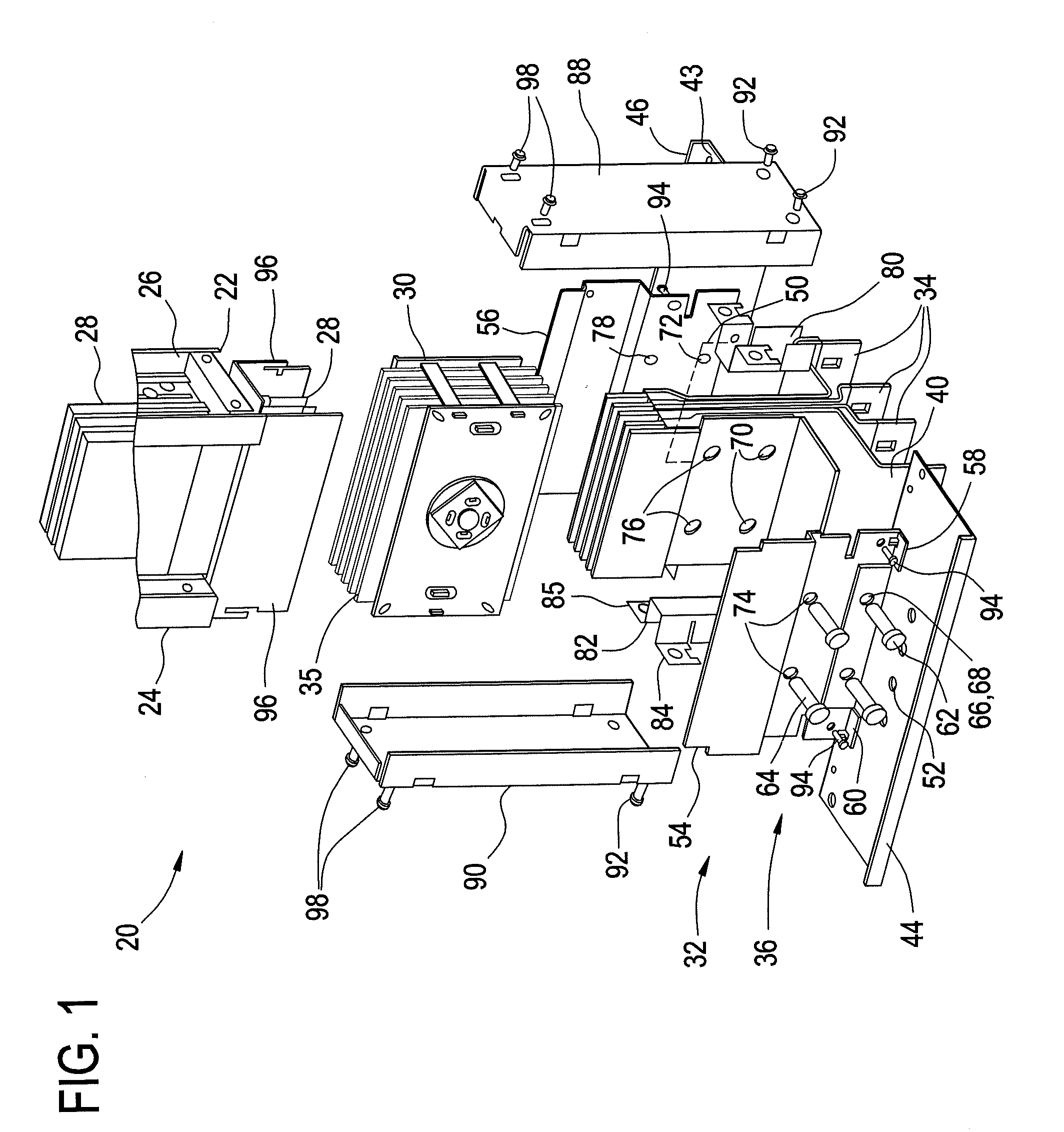
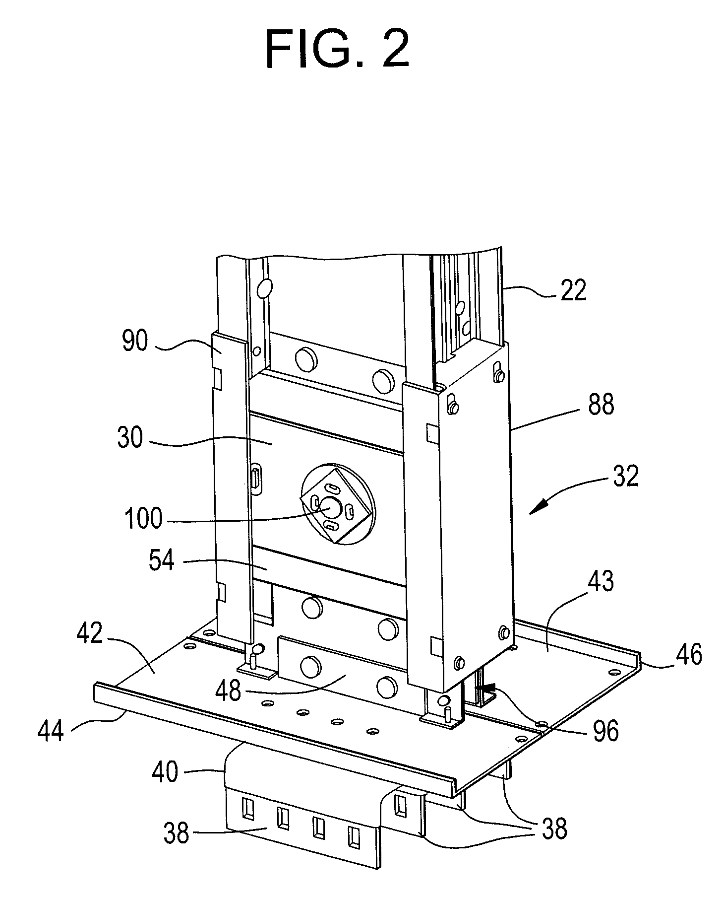
[0013]Busway systems 20 are used to transfer power within an electrical distribution system. The busway 20 typically includes a housing 22 made from extruded aluminum, but may employ other materials suitable for the purposes disclosed herein. The housing 22 is formed by interlocking a first half 24 with a second half 26. The housing 22 contains a plurality of busbars 28, where each of the busbars 28 carries a separate electrical phase. It should be appreciated that each of the individual busbars 28 is insulated from the other busbars 28. Busway 20 are formed in standard lengths, such as 20 feet for example, and may be interconnected with other busway by joint assemblies 30. Busway 20 may be further connected with members having other shapes to allow the routing of the busway 20 within an electrical distribution system. Busbars 28 are typically made from copper, but may be made from any other material suitable for the purposes disclosed herein, such as aluminum or copper-clad aluminu...


PUM


Abstract

A flange end stub for an electrical busway system is provided. The flange end stub includes a flange plate having a first and second tab extending perpendicular to a first surface. A pair of joint side plates is coupled to the first and second tab with one or more conductors extending through the flange plate in between the joint side plates. A first and second bracket is coupled in between the joint side plates on either side of the conductors. Covers are mounted to the first and second brackets and extend over the conductors and any joint assembly that is attached. The covers and brackets cooperate to provide ingress protection.

Description

BACKGROUND[0001]The present invention relates to an electrical busway system, and particularly relates to a system for coupling an electrical busway to equipment using a flange end stub connector.[0002]Electrical busway, also known as elongated electrical distribution busway, is well known in the art. An electrical busway housing system is typically comprised of multiple pieces of tract connected end to end with one or more electrically-isolated, conductive busbars fastened to the housing, such that the system is capable of conducting electricity end to end through the busbars. The busbar is also adapted to permit electrical power tap-off at any point along the length of the busbar. Such busbars are often provided overhead, or may be provided along walls or flooring, and are used to distribute electricity through various take-off devices to equipment, appliances, lighting or other articles requiring a source of electrical energy to operate. For example, when installed in a home or o...

Claims


Application Information

Patent Timeline
Patent Type & Authority Applications(United States)
IPC IPC(8): H02G5/00
CPCH01R25/145H02G5/10H02G5/007H01R25/14H01R25/16H02B1/20H02G5/00
Inventor BHATHIJA, KULDEEP KUMARCOX, JEFFERY LYNNRICHARD, STEVEN ENGLISH
Owner ABB (SCHWEIZ) AG
Why Eureka
Try Eureka