Spectacle lens frame shape measuring apparatus

a technology of shape measurement and spectacle lens, which is applied in the field of spectacle lens frame shape measurement apparatus, can solve the problems of adversely affecting measurement, unable to obtain the proper measurement value, and the shape of spectacle lens frame re and lf may not be obtained with high accuracy

Inactive Publication Date: 2010-03-18
KK TOPCON
View PDF8 Cites 19 Cited by
  • Summary
  • Abstract
  • Description
  • Claims
  • Application Information

AI Technical Summary

Benefits of technology

[0026]The present invention has been made in the light of the aforementioned circumstances, and an object of the present invention is to provide a spectacle lens frame shape measuring apparatus capable of prop...

Problems solved by technology

Accordingly, proper measurement values may not be obtained.
Accordingly, the shapes of the spectacle lens frames RE and LF may not be obtained with high accuracy.
This axial shift wi...

Method used


Image

  • Spectacle lens frame shape measuring apparatus
  • Spectacle lens frame shape measuring apparatus
  • Spectacle lens frame shape measuring apparatus

Examples


verification experiments

(Verification Experiments)

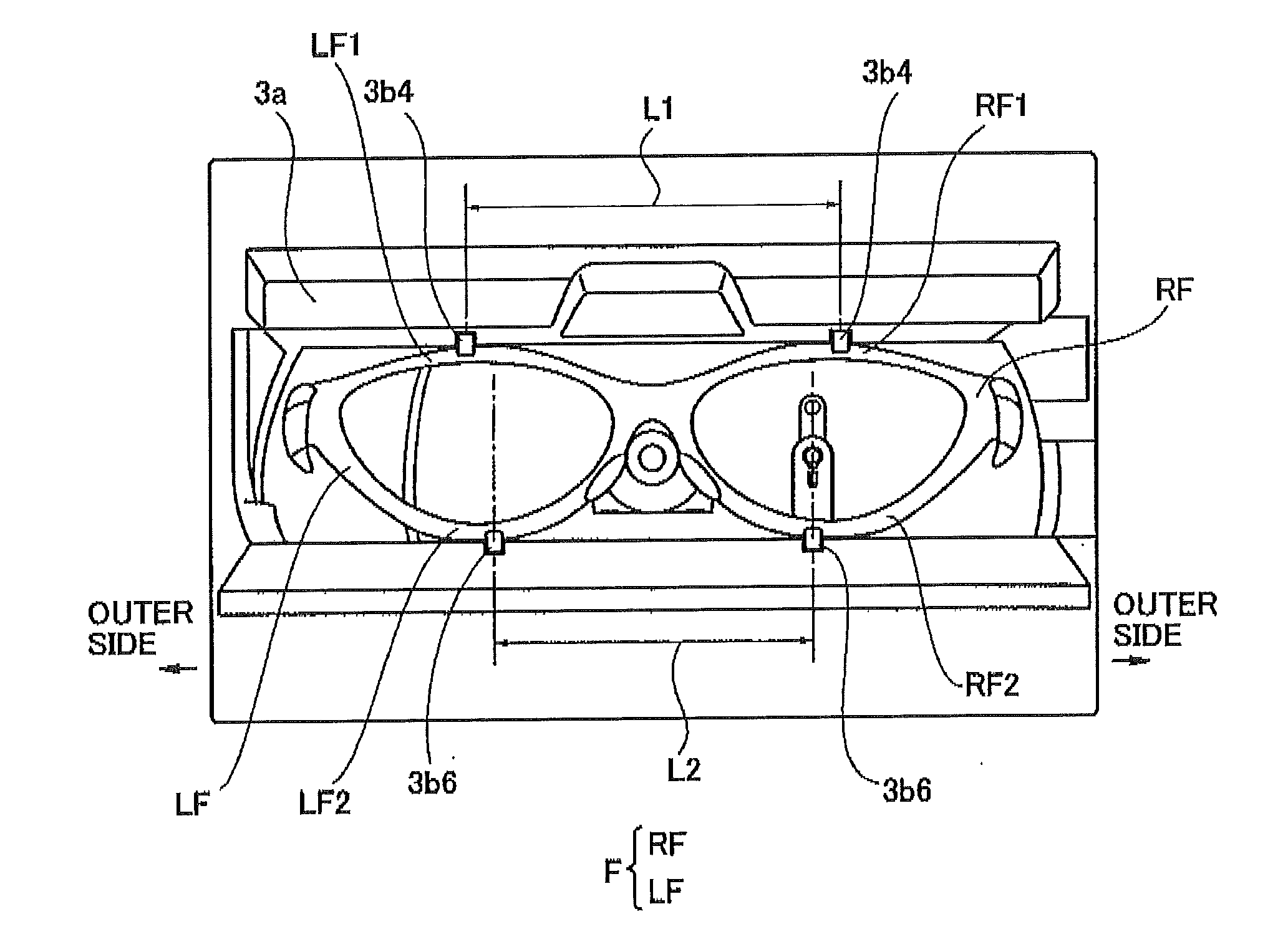
[0152]First, in the spectacle lens frame shape measuring apparatus of the aforementioned embodiment, the distance L2 between the lower holding bars 3b6 and 3b6 on a reference side is 70 mm, and the distance L1 between the upper holding bars 3b4 and 3b4 on a brow side is 85 mm. In such a spectacle lens frame shape measuring apparatus, a to-be-corrected tool with the curved angle θ1 was chucked.

[0153]The to-be-corrected tool was therefore inclined and chucked. Examination was made for the influence of the inclination on the distance FPD between geometric centers of the right and left lens frames RF and LF.

[0154]The to-be-corrected tool was a template (pattern) used instead of the spectacle lens frames. The to-be-corrected tool was not a template (pattern) corresponding to a single lens frame but a template corresponding to lens frames for right and left eyes. The tool was composed of a single plate with a predetermined size equivalent to a left eye lens frame...

modification 1

(Modification 1)

[0254]In the aforementioned embodiment, as shown in FIG. 23B, the bridge 201 includes the fixing plates 201c and 201d which abut on the rear refractive surfaces of the lenses Lm (ML) and Lm (MR), respectively; and the temple clasps 202 and 208 include the fixing plates 202b and 203b which respectively abut on the rear refractive surfaces of the lenses Lm (ML) and Lm (MR) as shown in FIG. 28B. However, the present invention is not necessarily limited to this.

[0255]For example, as shown in FIGS. 28A and 26B, the spectacle frame may have a configuration in which the fixing plates 201c and 201d respectively abut on front refractive surfaces of the lenses Lm (ML) and Lm (MR) and the temple clasps 202 and 203 include the fixing plates 202b ad 203b abutting on the front refractive surfaces of the lenses Lm (ML) and Lm (MR), respectively as shown in FIG. 26B.

[0256]In this case, the curvature of the front refractive surfaces of the lenses Lm (ML) and Tim (MR) and the circumfe...

modification 2

(Modification 2)

[0258]In the aforementioned embodiment, the attachment hole detection ranges (sensing ranges) Sa and Sb extending in the vertical direction of the lens Lm are set in the right and left parts of the lens Lm, but the present invention is not necessarily limited to this. For example, as shown in FIG. 27, a margin line 311 for measurement is set a predetermined amount (for example, 1 mm) inside of an outer circumferential surface 310 of the lens Lm based on the lens shape information (θ, ρi, Zbi), and an attachment hole detection range (a sensing range) Sc of a predetermined range (for example, 10 mm×10 mm) is set.

[0259]Then, as shown in FIG. 28, a number of measurement points Pi (for example, 200 points in a matrix) are provided in the attachment hole detection range (sensing range) Sc, and three dimensional, position information of the refractive surface of the lens Lm is measured at the 200 measurement points Pi in a matrix by the attachment hole probe 38. At this mea...


PUM


Abstract

A spectacle lens frame shape measuring apparatus includes a holding device including upper pins and lower pins respectively holding upper rims and lower rims of frames for a spectacle lens, the upper pins holding the frames at different positions in a right-left direction from the positions at which the lower pins hold the frames and being placed at a same height as the lower pins in a vertical direction, a probe brought into contact with lens fitting grooves of the frames held by the holding device, a swinging mechanism swinging the holding device around a predetermined virtual axis, and a calculation controller calculating an axial shift amount or angle of the frames held by the holding device on the basis of a carved angle of the frames and an inclination angle of any one of the upper and lower rims, and correcting a shape of the frames obtained by the probe in accordance with the calculated axial shift amount or angle.

Description

CROSS REFERENCE TO RELATED APPLICATIONS[0001]The present application is based on and claims priority from Japanese Application Number 2008′235915, filed on Sep. 16, 2008, the disclosure of which is hereby incorporated by reference herein in its entirety.BACKGROUND OF THE INVENTION[0002]1. Field of the Invention[0003]The present invention relates to a spectacle lens frame shape measuring apparatus measuring the shape of a lens (a lens frame or a frame) of spectacles and specifically relates to an improvement of the measuring apparatus in which upper holding pins hold upper rims of spectacle lens frames at different positions in a right-left direction from positions at which lower holding pins hold lower rims thereof.[0004]2. Description of the Related Art[0005]For processing lenses to be attached to a spectacle lens frame, it is necessary to previously measure the shape of the spectacle lens frame. As an apparatus for measuring the shape of the spectacle lens frame, a spectacle lens ...

Claims


Application Information

Patent Timeline
IPC IPC(8): G01B5/20
CPCG01B5/20G01B21/20G02C13/00
Inventor MIYASHITA, KENJI
Owner KK TOPCON
Why Eureka
Try Eureka