Rotate-to-advance catheterization system

a technology of rotating to advance catheterization and gastrointestinal passages, which is applied in the field of apparatus and methods for catheterization and related treatments of the genitourinary and gastrointestinal passages of mammals, can solve the problems of failure to recognize the fundamental flaws and fundamental shortcomings of failure to resolve the critical features of the structure, and inability to realize the fundamental flaws and abandon the basic push-to-advance technique, so as to

Active Publication Date: 2010-03-18
OLYMPUS ENDO TECH AMERICA
View PDF101 Cites 45 Cited by
  • Summary
  • Abstract
  • Description
  • Claims
  • Application Information

AI Technical Summary

Benefits of technology

[0154]It should be appreciated that the system of the present invention can be rotated either manually (e.g., by the surgeon rotating the catheter by hand) or, alternatively, the system can be power driven. In a preferred form of the present invention, a powered drive may be used to rotate the catheter so as to allow an easier and more precise advancement of the catheter into the bodily passageway or retraction of the catheter from the bodily passageway.
[0155]In one preferred form of the present invention, a lavage system may be provided for clearing away debris from the front of the catheter. In many situations, the bodily passageway receiving the catheter may be obscured with debris, and it may be helpful to have a clear view of the anatomy when advancing an endoscope through the bodily passageway. A lavage system may be provided to flush debris from the cavity passageway with fluid during the insertion of the endoscope. By way of example, the lavage system may be used to break up and remove fecal matter from the colon, thereby enabling a clearer view of the anatomy when the catheter is being advanced through the colon.

Problems solved by technology

There has been patent activity in the prior art indicating dissatisfaction with the push-to-advance methodology.
In all cases, these disclosures fail to recognize that the basic push-to-advance technique is fundamentally flawed and should be abandoned, and fail to resolve the critical features of structure necessary for rotational advancement as a substitute for the push-to-advance method.
Such disclosures likewise reveal a reliance on push-in methods, or an assumption that such structures can be pulled out without regard to the spiral features, again failing to recognize rotation as a viable substitute for pushing, and failing to resolve the critical features of structure necessary for effective rotational advancement.
As a further indication of the failure of the prior art to provide effective improvements to traditional push-in methods, there is no apparent indication among the products commercially available, or in the medical practices known to the Applicants, that any of these spirally-ornamented devices were ever found to be clinically viable.
This device takes a high level of skill to use, is difficult to maneuver and can be very painful for the patient, due to the basic push-to-advance design that has not changed since the device was invented in the early 1960's.
The so-called “insertion tube”, which makes up the rest of the endoscope's 60-150 cm length, is not capable of controlled deflection.
To inspect the whole length of the large intestine requires a highly skilled practitioner, which makes the procedure costly.
Even still, the procedure can be very painful for the patient, making sedation necessary.
This is due to the inherent deficiencies in the “push-to-advance” design.
Due to the significant differences in both the diameters and lengths of the small bowel and the large bowel, traditional endoscopes and the methods used in large bowel applications are not ideal for investigating the small bowel.
This is because of the need to gather (or pleat) the small bowel onto the endoscope, which is difficult to accomplish using traditional endoscopes.
This process is extremely time-consuming for both the physician performing the procedure and the patient undergoing it.
Similarly, the longer the procedure, the greater the risk of anesthesia-related complications.

Method used


Image

  • Rotate-to-advance catheterization system
  • Rotate-to-advance catheterization system
  • Rotate-to-advance catheterization system

Examples


Embodiment Construction

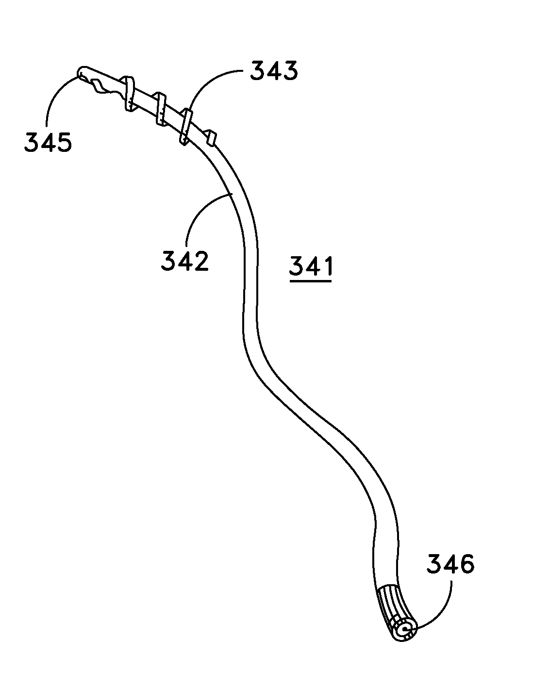
[0156]In one preferred form of the invention, there is provided a method for visualizing the interior of a bodily passageway at a remote location, the method comprising the steps of:

[0157]providing a visualization system for deployment in the bodily passageway, the visualization system comprising:[0158]a tube having a distal end and a proximal end, at least a portion of the distal end being rotatable relative to the proximal end;[0159]visualization apparatus disposed within the lumen of the tube; and[0160]a helical thread disposed on the exterior surface of the rotatable portion of the distal end of the tube, the helical thread having a sufficient structural integrity, and a sufficient surface profile, such that when the tube is disposed in the bodily passageway so that the helical thread engages the interior side wall of the bodily passageway, rotation of the rotatable portion of the distal end of the tube will induce a relative movement between the tube and the side wall of the bo...


PUM


Abstract

A method for visualizing the interior of a bodily passageway at a remote location, the method comprising the steps of:
    • providing a visualization system for deployment in the bodily passageway, the visualization system comprising:
      • a tube having a distal end and a proximal end, at least a portion of the distal end being rotatable relative to the proximal end;
      • visualization apparatus disposed within the lumen of the tube; and
      • a helical thread disposed on the exterior surface of the rotatable portion of the distal end of the tube, the helical thread having a sufficient structural integrity, and a sufficient surface profile, such that when the tube is disposed in the bodily passageway so that the helical thread engages the interior side wall of the bodily passageway, rotation of the rotatable portion of the distal end of the tube will induce a relative movement between the tube and the side wall of the bodily passageway;
    • inserting the visualization system into the bodily passageway at a location remote from the site which is to be visualized;
    • rotating the rotatable portion of the distal end of the tube so as to bring together the site which is to be visualized and the visualization apparatus; and
    • using the visualization apparatus to visualize the interior of the bodily passageway.

Description

REFERENCE TO PENDING PRIOR PATENT APPLICATIONS[0001]This patent application:[0002](i) is a continuation-in-part of pending prior U.S. patent application Ser. No. 11 / 189,561, filed Jul. 26, 2005 by James J. Frassica for ROTATE TO ADVANCE CATHETERIZATION SYSTEM (Attorney's Docket No. FA-63 CIP CON 3);[0003](ii) is a continuation-in-part of pending prior U.S. patent application Ser. No. 11 / 121,751, filed May 4, 2005 by James J. Frassica for ROTATE-TO-ADVANCE CATHETERIZATION SYSTEM (Attorney's Docket No. FA-70 CON);[0004](iii) is a continuation-in-part of pending prior U.S. patent application Ser. No. 11 / 363,990, filed Feb. 28, 2006 by James J. Frassica et al. for ROTATE-TO-ADVANCE CATHETERIZATION SYSTEM (Attorney's Docket No. FA-71);[0005](iv) is a continuation-in-part of pending prior U.S. patent application Ser. No. 11 / 437,979, filed May 19, 2006 by James J. Frassica et al. for ROTATE-TO-ADVANCE CATHETERIZATION SYSTEM (Attorney's Docket No. FA-72);[0006](v) is a continuation-in-part ...

Claims


Application Information

Patent Timeline
Patent Type & Authority Applications(United States)
IPC IPC(8): A61B1/00
CPCA61B17/12099A61B17/12109A61B17/12136A61B17/12159A61M25/0017A61M25/0068A61M2025/1086A61M25/0075A61M25/0105A61M25/10A61M27/008A61M2025/006A61M2025/0191A61M25/007A61B1/00148
Inventor FRASSICA, JAMES J.AILINGER, ROBERT E.
Owner OLYMPUS ENDO TECH AMERICA
Why Eureka
Try Eureka