
Intervertebral disc prosthesis and method for implanting and explanting

a technology for intervertebral discs and prostheses, applied in the field of prostheses for intervertebral discs, can solve the problems of slight tension, abutting vertebrae are still slightly distracted, and the adjacent vertebrae are still slightly abutted, and achieve the effects of quick and easy implantability, rapid and easy explantation, and quick and easy implantation

Active Publication Date: 2010-03-18
MAYER PETER L
View PDF81 Cites 17 Cited by
  • Summary
  • Abstract
  • Description
  • Claims
  • Application Information

AI Technical Summary

Benefits of technology

[0013]It is accordingly an object of the invention to provide a novel intervertebral disc prosthesis that is quickly and easily implantable, a method for quickly and easily implanting and a method for quickly and easily explanting the novel intervertebral disc prosthesis in the event the indications are such that removal of the prosthesis is desirable. The prosthesis of the present invention overcomes the above-mentioned disadvantages of known prosthesis of this general type. The foregoing object of the invention is accomplished by the novel disc prosthesis of the present invention, which consists of an elongated metal, ceramic or hard plastic, biocompatible implant that has a shape suitable for insertion into the nucleus pulposus of a degenerative intervertebral disc to restore normal body motion with respect to the adjacent and abutting vertebrae. The implant is placed through the disc annulus laterally and extends from one side to the other and has caps or heads on its ends that bear against the adjacent vertebrae, so that it is held in position. It is not meant for fusion, but rather is meant to allow for natural or near natural motion of the spine. When implanted, the disc prosthesis has a height slightly greater than the normal disc spatial opening and thus, slightly distracts the adjacent and abutting vertebrae. It can be used for cervical, thoracic or lumbar degenerative discs.
[0021]The locking member of the prosthesis and the second or distal head can have quick detachable mutually coacting elements that prevent longitudinal movement of the locking member relative to the second head. The quick detachable mutually coacting elements can comprise projecting flat bars peripherally arranged in a hex shape at the end of the locking member, each bar having peripherally extending bump coacting with a shoulder defined in the hex opening of the second or distal member. The first and second heads can have flat surfaces facing inwardly toward the main prosthesis body that can bear against the annular wall and the abutting vertebrae when the prosthesis is implanted in the disc, but without too much pressure so that relative rotation is not impeded. The opening in said first or proximal head can be hex shaped and the locking member can have a hex shaped end that fits into the hex opening of the first head in a recessed manner. The hex shaped openings and the coacting hex shaped elements can have other shapes, such as, square, diamond, cruciform, triangular, octagonal or any other non-circular shape.

Problems solved by technology

However, because the height of the main body of the prosthesis is greater than the height of the disc space, the adjacent, abutting vertebrae are still slightly distracted and under slight tension.

Method used


Image

  • Intervertebral disc prosthesis and method for implanting and explanting
  • Intervertebral disc prosthesis and method for implanting and explanting
  • Intervertebral disc prosthesis and method for implanting and explanting

Examples


Embodiment Construction

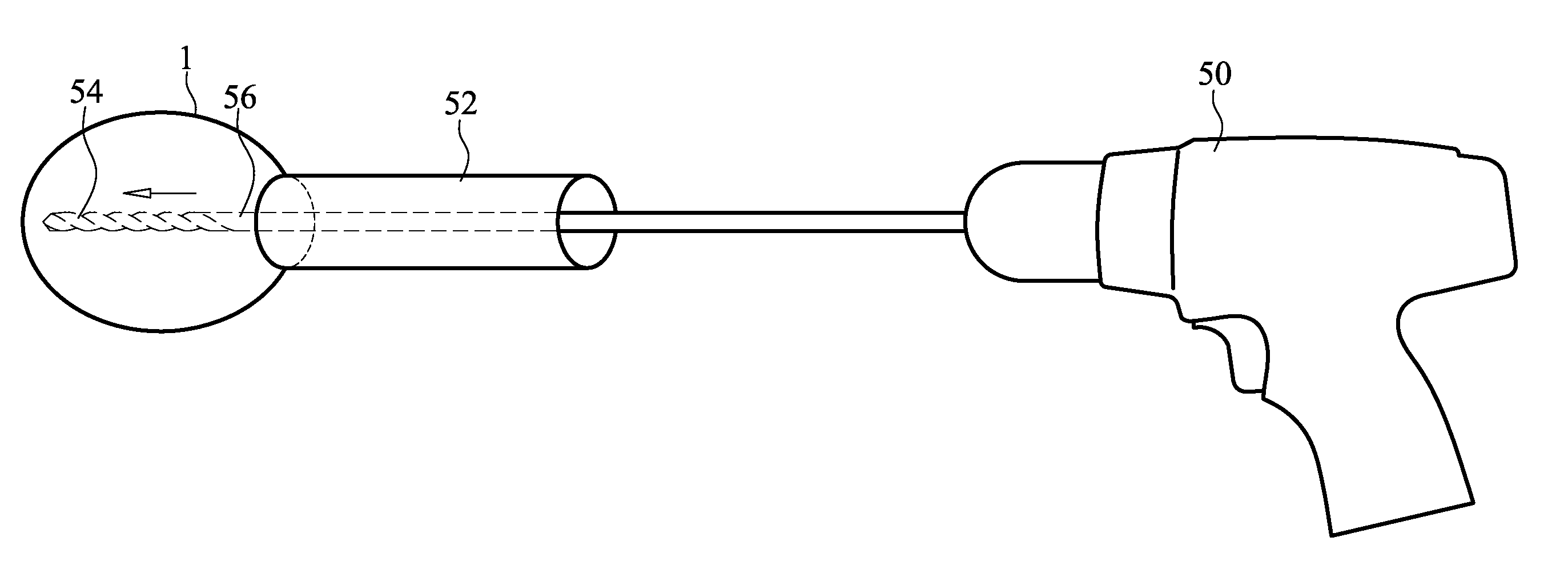
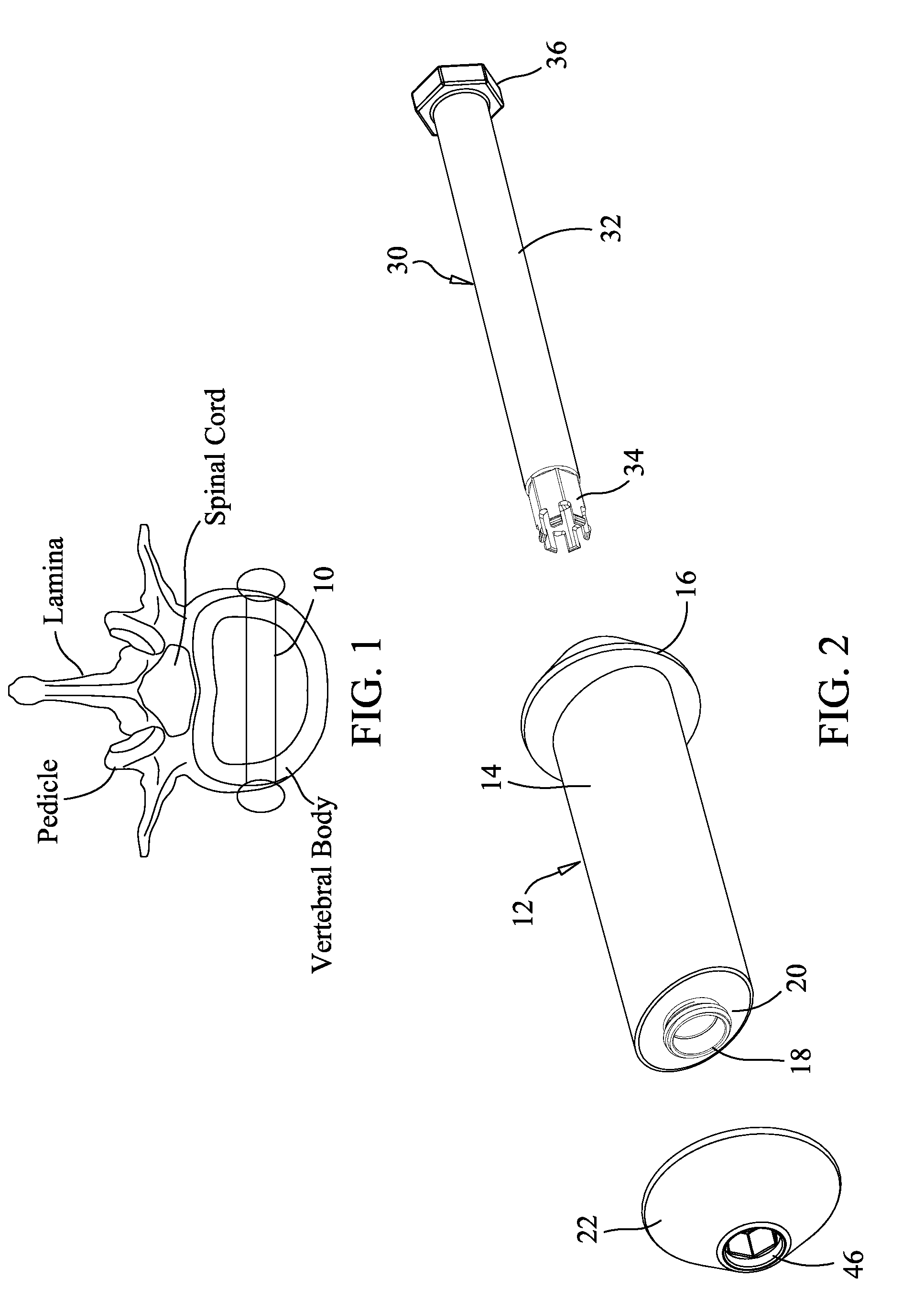
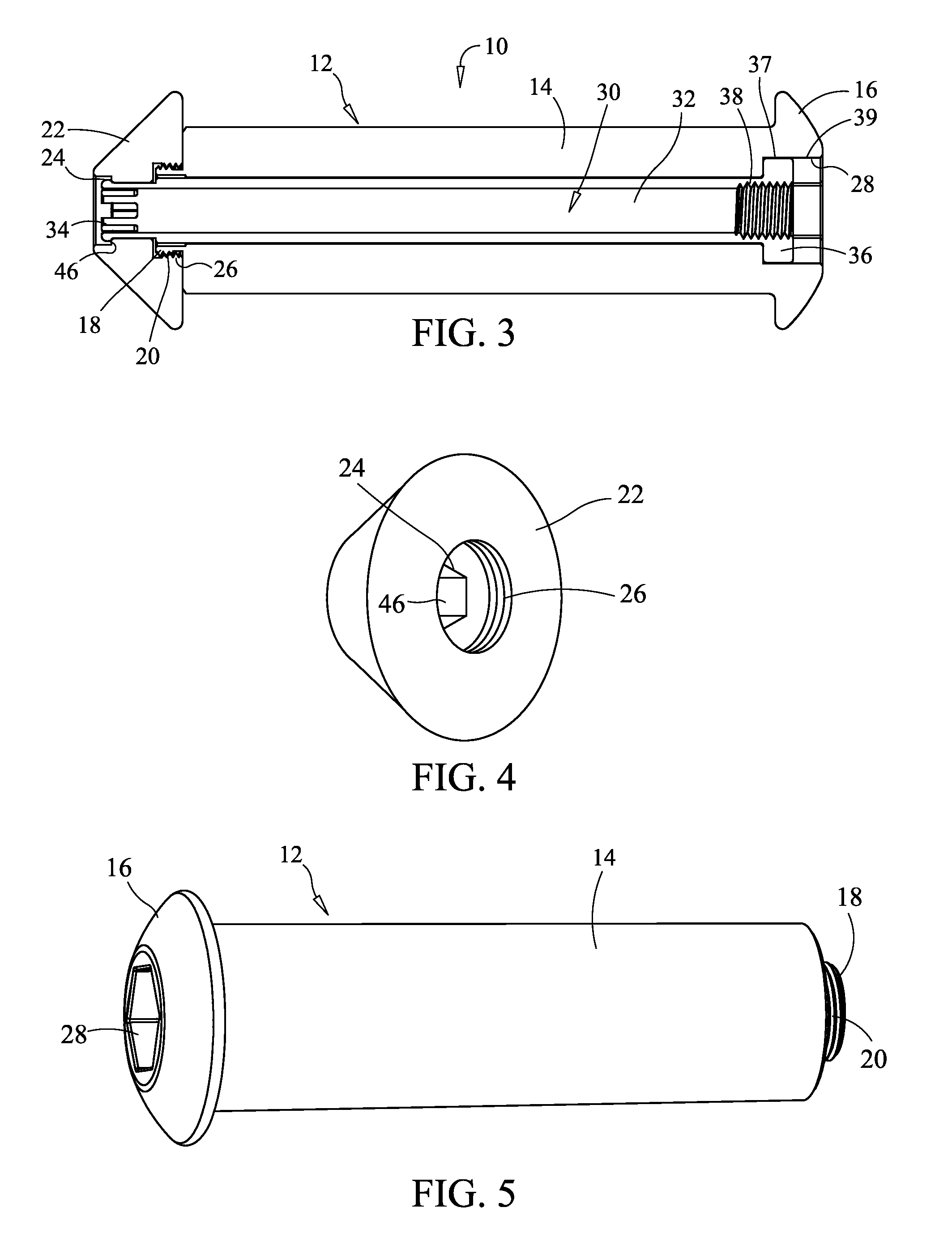
[0071]Referring now to the figures of the drawing in detail and first, particularly to FIGS. 1 to 7 and 18 to 21, the prosthesis of the present invention will be described structurally first and then the method of implanting laterally in an intervertebral disc 1. As shown in FIG. 3, for example, the prosthesis 10 consists of (i) a main prosthesis body 12 in the form of an elongated cylindrical tube 14 having a cap 16 with a recessed hex opening 28 integrally formed at one end and a reduced section 18 at its other end formed with a thread 20, (ii) a cap 22 formed with a recessed hex opening 24 (smaller in diameter than recess hex opening 28) on its side facing outwardly and a recessed threaded section 26 on its side facing inwardly for attachment to the threaded reduced section 18, and (iii) a hex locking member 30 in the form of an elongated tube or rod 32 having at one end a hex form 34 that fits into and mates with the hex opening 24 of cap 22, and at its other end an enlarged hex...


PUM

PropertyMeasurementUnit
heightaaaaaaaaaa
widthaaaaaaaaaa
vertical heightaaaaaaaaaa

Abstract

Prosthesis for inserting into a damaged intervertebral disc having an elongated tubular main prosthesis body with a length to fit laterally from one side of a disc to the other at its mid-plane. The main prosthesis body has a vertical height slightly greater than the height of normal disc space of the damaged intervertebral disc into which it is to be implanted, and a shape in cross section normal to its longitudinal axis so that main prosthesis body makes appropriate contact with vertebrae abutting to the damaged intervertebral disc. Heads having a vertical height greater than the vertical height of the main prosthesis body are mounted on the ends of the main prosthesis body. A method for implanting from one side only and a method for explanting from one side only.

Description

BACKGROUND OF THE INVENTION[0001]1. Field of the Invention[0002]The invention relates to prostheses for intervertebral discs that are easily and quickly implantable, a method for easily and quickly implanting and a method for easily and quickly explanting.[0003]2. Description of the Related Art[0004]Intervertebral discs (or more simply “discs”) lie between adjacent vertebrae in the spine. Each disc forms a cartilaginous joint to allow slight movement of the vertebrae and acts as a ligament to hold the vertebrae together.[0005]Discs include an outer annulus fibrosus, which surrounds the inner nucleus pulposus. The annulus fibrosus includes several layers of fibrocartilage. The nucleus pulposus contains loose fibers suspended in a mucoprotein gel, which has the consistency of semi-hard and slightly fibrous connective tissue or cartilage. The nucleus of the disc acts as a shock absorber for distributing pressure evenly across the disc and for absorbing the impact of bending and twistin...

Claims


Application Information

Patent Timeline
Patent Type & Authority Applications(United States)
IPC IPC(8): A61F2/44A61B17/58
CPCA61F2/30744A61F2310/00179A61F2/442A61F2/447A61F2/4611A61F2002/2817A61F2002/30024A61F2002/30075A61F2002/30224A61F2002/30405A61F2002/30426A61F2002/30509A61F2002/3051A61F2002/30512A61F2002/449A61F2002/4619A61F2002/4627A61F2002/4629A61F2002/464A61F2210/0061A61F2220/0025A61F2230/0069A61F2250/0021A61F2310/00011A61F2/441A61F2/4637A61F2002/30507
Inventor MAYER, PETER L.
Owner MAYER PETER L
Learn More