
Dual condition fire/smoke detector with adjustable LED cannon

a technology of led cannon and fire/smoke detector, which is applied in the direction of fire alarm, smoke/gas actuation, signalling system, etc., can solve the problems of inhibiting the ability to safely and quickly escape from a hazard, unable to identify the origin of flashing lights in a smoky room, and reducing the false alarm rate. , to achieve the effect of enhancing early warning notification and minimizing false alarms

Inactive Publication Date: 2010-03-25
L I F E SUPPORT TECH
View PDF23 Cites 61 Cited by
  • Summary
  • Abstract
  • Description
  • Claims
  • Application Information

AI Technical Summary

Benefits of technology

[0007]The present invention is for a dual condition fire / smoke detector system. The system includes a fire / smoke detector having a housing with a photoelectric sensor and a heat sensor disposed therein. In another embodiment of the present invention, the fire / smoke detector includes a sensor comprising at least two of a photoelectric sensor, a heat sensor, an ionization sensor or a carbon monoxide sensor disposed within the housing. Additionally, the fire / smoke detector may include a means associated with the sensors for minimizing false alarms. Any of the aforementioned sensors and the false alarm minimization means provide enhanced early warning notification of fire hazards while preventing false alarms.

Problems solved by technology

While these devices can be useful in some circumstances, the flashing incandescent lights can daze or confuse people rather than provide direction.
It can be particularly difficult to identify the origination of flashing lights in a smoky room.
Furthermore, intense flashing lights also destroy night vision and often confuse people trying to escape from a dark building, thereby inhibiting the ability to safely and quickly escape from a hazard.
When properly mounted to the ceiling, the network of smoke detection devices in Kelly is unable to communicate with other devices outside a room unless the laser beam was able to penetrate walls, bend around corners or penetrate floors or ceilings.
This is particularly disadvantageous as the identification of a hazard in one part of a building could not be communicated to a person in another part of the building (e.g. a separate floor).

Method used


Image

  • Dual condition fire/smoke detector with adjustable LED cannon
  • Dual condition fire/smoke detector with adjustable LED cannon
  • Dual condition fire/smoke detector with adjustable LED cannon

Examples


Embodiment Construction

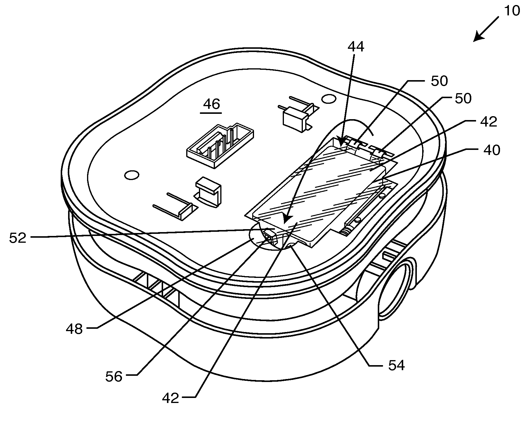
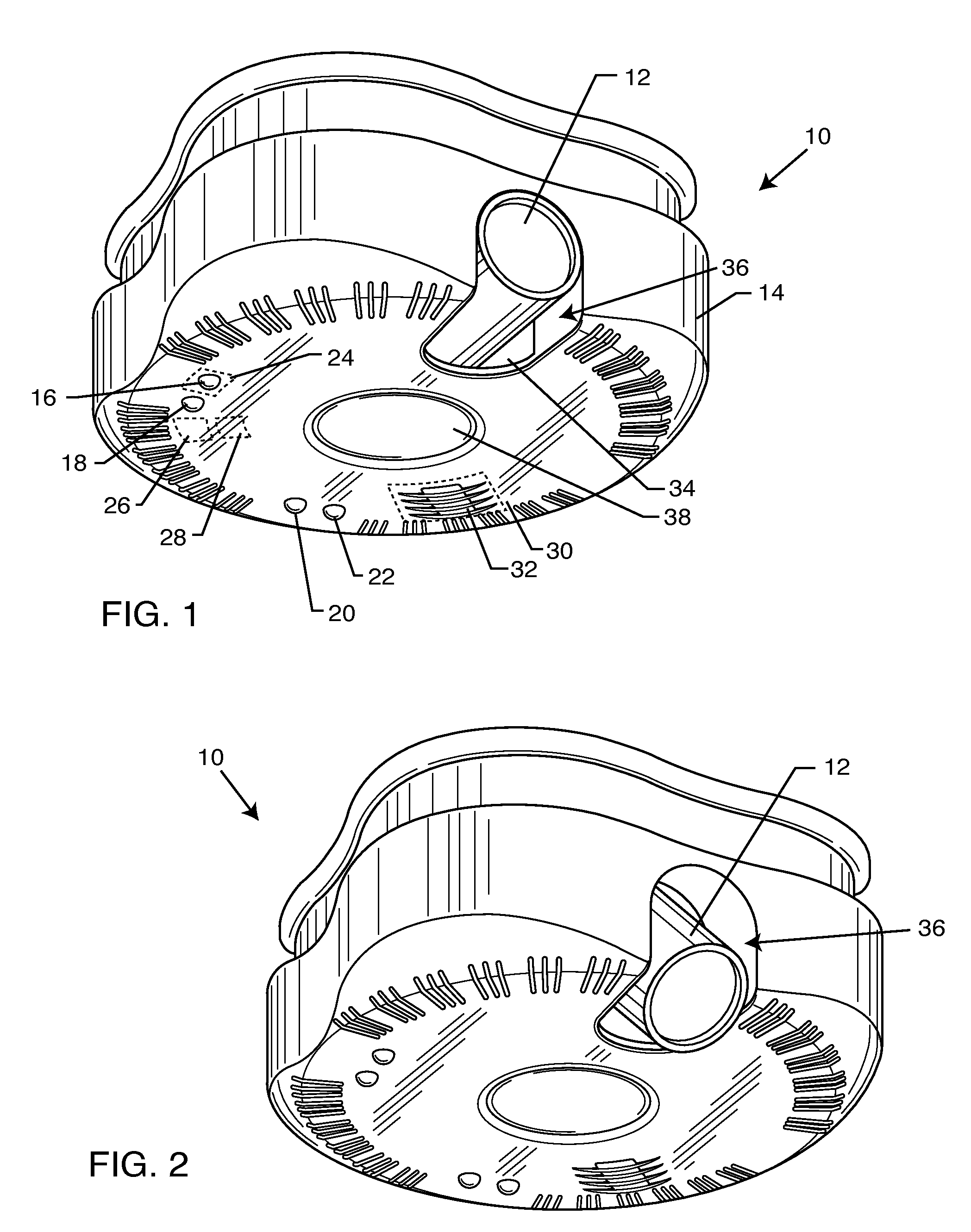
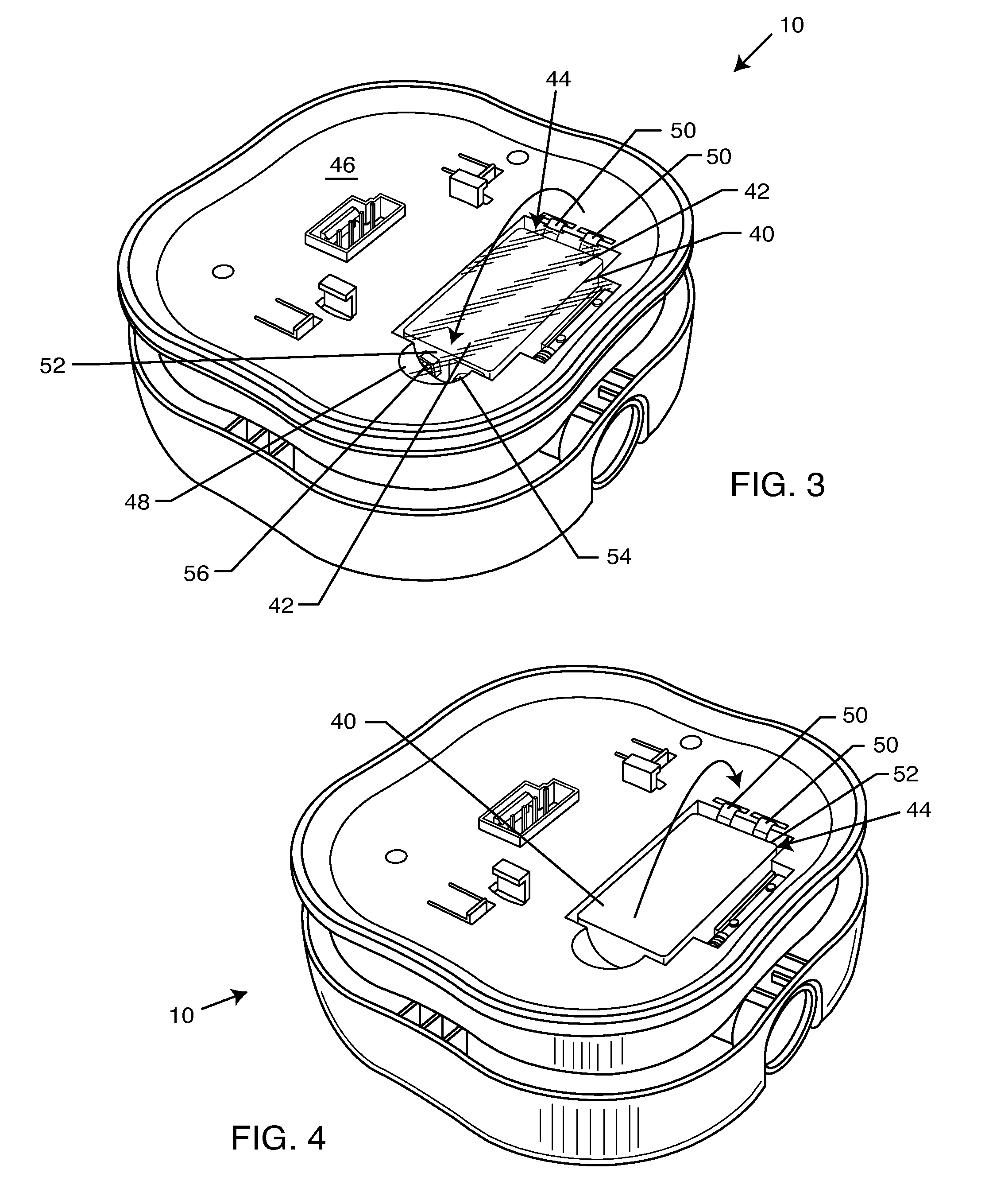
[0026]As shown in the drawings for purposes of illustration, the present invention for a dual condition detector is referred to generally by the reference number 10. In FIG. 1, the dual condition detector 10 is shown including a light cannon 12 within an outer case 14 of the dual condition detector 10. Protruding from the outer case 14 includes a sensor LED 16, a transmitter / receiver LED 18, a power indicator LED 20 and a battery indicator LED 22. Accordingly, the dual condition detector 10 is equipped with any one of a number of sensors (designated by the sensor circuitry 24 in FIG. 1) that include a photoelectric sensor, an ionization sensor, a heat sensor or any other smoke or fire sensor known in the art. These sensors 24 (one or more) are electrically coupled to the sensor LED 16 for providing external notification regarding the operating condition of the sensor 24. The dual condition detector 10 may include multiple sensor LEDs 16 for each sensor 24. Preferably, the dual condi...


PUM


Abstract

A dual condition fire / smoke detector system includes a housing and a sensor comprising at least two of a photoelectric sensor, a heat sensor, an ionization sensor or a carbon monoxide sensor disposed within the housing. A wireless communication system associated with the sensor enables communication of the detector with a remote device via a wireless receiver and a wireless transmitter. A light source associated with the housing may be positioned to illuminate an exit in response to a hazard detected by any of the aforementioned sensors.

Description

BACKGROUND OF THE INVENTION[0001]The present invention relates to a dual condition fire / smoke detector with adjustable LED cannon. More particularly, the invention relates to fire / smoke detector capable of communicating with other fire / smoke detectors to cooperatively indicate an escape route by coordinating individual adjustable LED cannons.[0002]Smoke alarms and detectors are generally well known in the art. One example of a modern smoke alarm is disclosed in U.S. Pat. No. 4,827,244 to Bellavia et al. Bellavia discloses a system for testing a remotely located detection unit. This is accomplished by using a flashlight or other item capable of directing a beam of radiant energy toward a photo sensor located on the detector unit. U.S. Pat. No. 4,166,960 to Meilla discloses a smoke detector having a radiation source for producing a directed radiation beam capable of sensing scattered smoke particles therein. Blockage of the radiation beam within the smoke detector causes the smoke det...

Claims


Application Information

Patent Timeline
IPC IPC(8): G08B17/12G08B17/10
CPCG08B17/10G08B7/062G08B17/113
Inventor LAX, SAMUEL
Owner L I F E SUPPORT TECH
Learn More