Power Line Communication Using Frequency Hopping

a power line and frequency hopping technology, applied in the field of advanced metering infrastructure, can solve the problems of power line circuits with only limited ability to carry higher frequencies, circuits may be many miles long, and propagation problems are limiting factors

Inactive Publication Date: 2010-03-25
ITRON NETWORKED SOLUTIONS INC
View PDF3 Cites 65 Cited by
  • Summary
  • Abstract
  • Description
  • Claims
  • Application Information

AI Technical Summary

Problems solved by technology

Since the power wiring system was originally intended for transmission of AC power at a nominal frequency of, e.g., 50 or 60 Hz, the power line circuits have only a limited ability to carry higher frequencies.
This propagation problem is a limiting factor for each type of power line communications.
However, these circuits may be many miles long.
However, variations in the physical characteristics of the electricity network and the current lack of IEEE standards mean that provisioning of the service is far from being a standard, repeatable process.
Known PLC systems have a number of issues.
The primary one is that power lines are inherently a very noisy environment.
Energy-saving devices often introduce noisy harmonics into the line.
However, BPL signals cannot readily pass through transformers, as their high inductance makes them act as low-pass filters, blocking high-frequency signals.
However, delivering BPL over the power grid in a typical U.S. city requires an order of magnitude more repeaters than in a comparable European city.
On the other hand, since bandwidth to the transformer is limited, this can increase the speed at which each household can connect, due to fewer people sharing the same line.
Another issue is signal strength and operating frequency.
Power lines are unshielded and will act as antennas for the signals they carry, and have the potential to interfere with shortwave radio communications.
In the case of autonomous transmissions by the various units, however, such an approach becomes impractical.

Method used


Image

  • Power Line Communication Using Frequency Hopping
  • Power Line Communication Using Frequency Hopping

Examples


Embodiment Construction

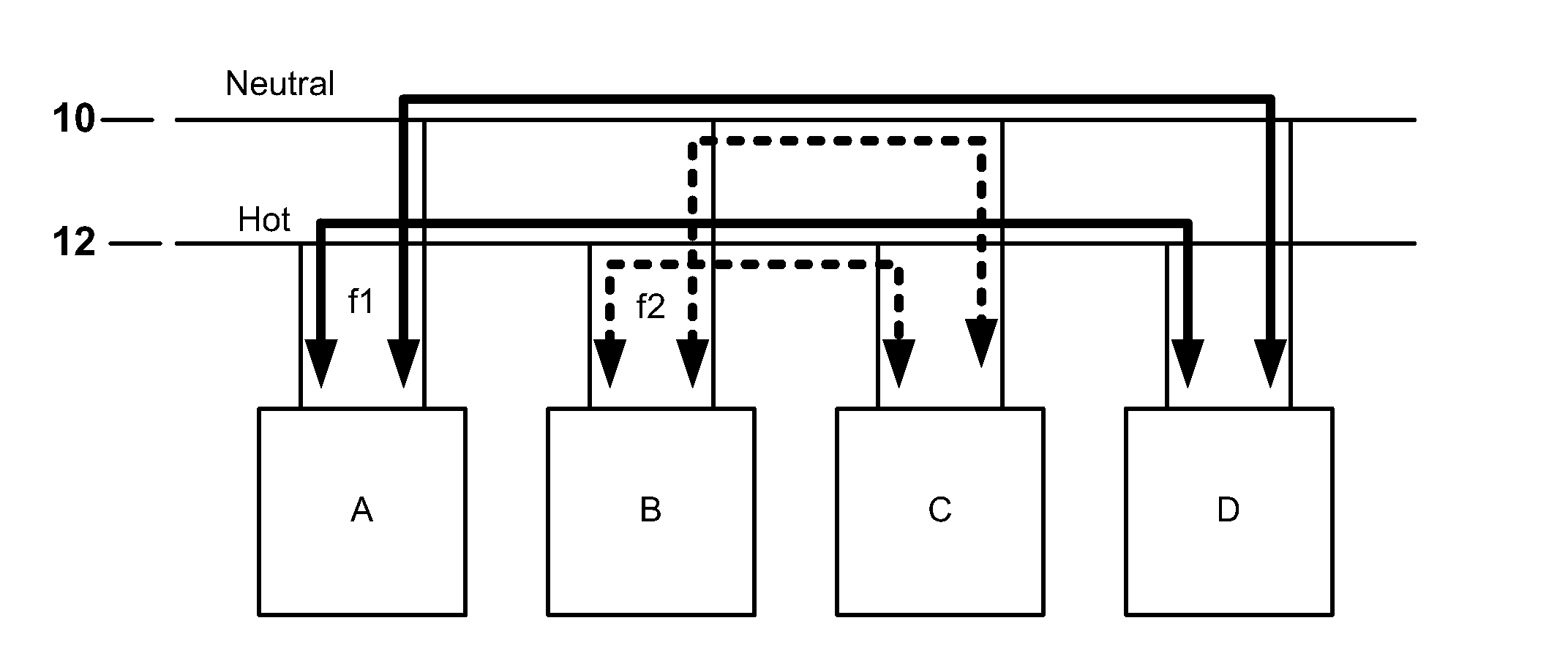
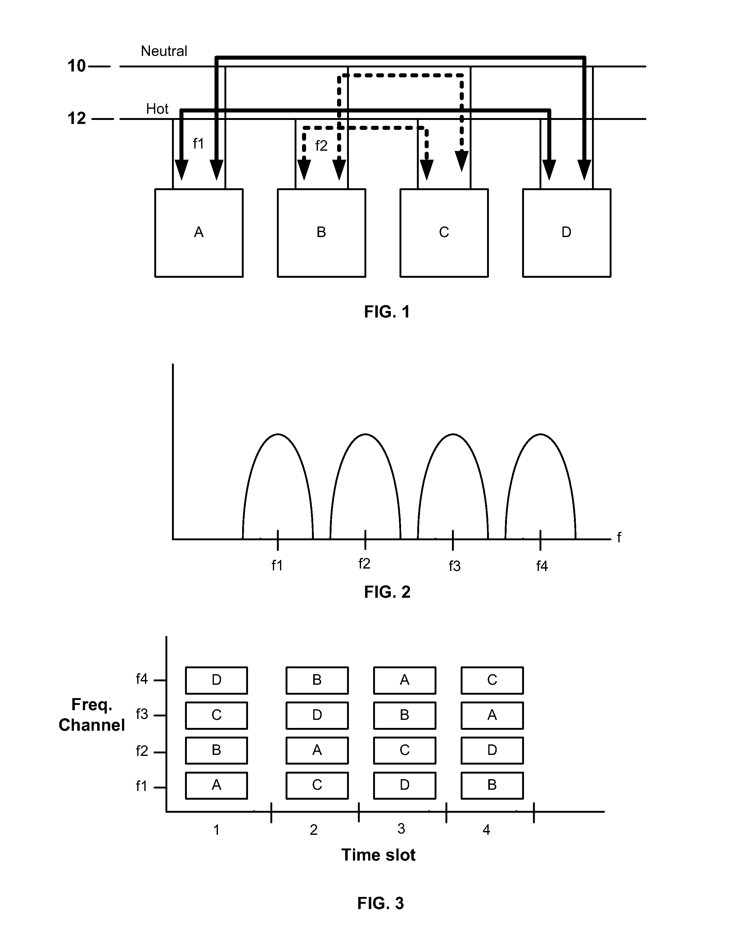
[0029]In accordance with the embodiments described hereinafter, the available spectrum on the power lines for the carrier signals is divided into several non-overlapping channels, so that communication between pairs (or groups) of nodes, e.g., meters, can, by simple selection of different channels, occur simultaneously. An exemplary implementation is shown in FIG. 1. A first pair of nodes, A and D, which communicate via power lines 10 and 12, do so via a first carrier frequency f1, depicted by the heavy solid lines. A second pair of nodes, B and C, communicate with each other at the same time via a second carrier frequency f2, as shown by the broken lines. Although only two nodes are involved in each set of communications in the example shown, it will be appreciated that a node can transmit to multiple nodes simultaneously at the designated frequency.

[0030]FIG. 2 is a frequency spectrum chart showing the separate non-overlapping frequency channels for the carrier signal. In the illu...


PUM


Abstract

Communications among multiple nodes via a shared power line medium are carried out by dividing the available frequency spectrum in the shared power line medium into plural non-overlapping channels. A first channel is assigned to a first group of nodes, and a second channel, different from the first channel, is assigned to a second group of nodes. Communications between the first group of nodes can occur simultaneously with communications between the second group of nodes via the shared power line medium. Time slots may be assigned for the communications between the first group of nodes that occurs simultaneously with the communications between the second group of nodes via the shared power line medium. The simultaneous communications between different groups of nodes via a shared power line medium may be implemented using a frequency-hopping spread spectrum technique.

Description

CROSS-REFERENCE TO RELATED APPLICATIONS[0001]This disclosure claims priority from U.S. Provisional Patent Application Ser. No. 61 / 099,041, filed Sep. 22, 2008, the content of which is hereby incorporated by reference in its entirety.BACKGROUND[0002]1. Field of the Invention[0003]The disclosed subject matter is generally directed to Advanced Metering Infrastructure (AMI), via which data is communicated between a utility, such as an electric power company, and meters that are located at the premises of the customers of the utility. The exemplary embodiments are particularly aimed at efficient and economical communications between the meters and servers at the back office or other central facility of the utility.[0004]2. Description of Related Art[0005]Power line carrier (PLC) or power line communications, also known as Power line Digital Subscriber Line (PDSL), mains communication, power line telecom (PLT), or power line networking (PLN), is a system for carrying data on a conductor a...

Claims


Application Information

Patent Timeline
Patent Type & Authority Applications(United States)
IPC IPC(8): H04B1/713
CPCH04B1/7156H04B2203/5445H04B2203/5433H04B3/54
Inventor FLAMMER, III, GEORGE
Owner ITRON NETWORKED SOLUTIONS INC
Why Eureka
Try Eureka