Eureka AIR delivers breakthrough ideas for toughest innovation challenges, trusted by R&D personnel around the world.

Method for selecting and manipulating a graphical object in an interactive input system, and interactive input system executing the method

Active Publication Date: 2010-04-01
SMART TECH INC (CA)
View PDF80 Cites 66 Cited by
  • Summary
  • Abstract
  • Description
  • Claims
  • Application Information

AI Technical Summary

Benefits of technology

[0027]in the event that one or more touch points coincide with a location of the graph

Problems solved by technology

According to the general principles of FTIR, the total internal reflection (TIR) of light traveling through an optical waveguide is frustrated when an object such as a pointer touches the waveguide surface, due to a change in the index of refraction of the waveguide, causing some light to escape from the touch point.
One drawback with systems requiring such touch precision on the part of the user is that the user may find it difficult to select a small widget.
Furthermore, interactive input systems of this nature do not typically employ useful feedback subsystems employing, for example, haptics.
However, the method is unable to determine whether the user intends to select a distant target versus one nearby.
Thus the presence of distant objects can make selection difficult for a nearby target.
However, this requires a significant amount of screen real estate and limits the amount of content that can be placed on a smaller display.
However, area cursors are problematic in dense target spaces where multiple targets could be contained in a single area cursor.
However, problems could arise when there are multiple targets, as each would slow down the cursor as it approached.
Although this effectively increases target width (since the bubble gets bigger), and decreases target distance (because less distance needs to be traveled to reach the target), if other targets, or distracters are nearby and within close proximity to the chosen target the size of the bubble is limited and can be much smaller.
As will be appreciated, although the above-described techniques improve the user experience of selecting and manipulating graphic widgets, the possibilities of user interaction with interactive input systems have not been fully exploited.

Method used


Image

  • Method for selecting and manipulating a graphical object in an interactive input system, and interactive input system executing the method
  • Method for selecting and manipulating a graphical object in an interactive input system, and interactive input system executing the method
  • Method for selecting and manipulating a graphical object in an interactive input system, and interactive input system executing the method

Examples


Embodiment Construction

[0062]In the following, a method for selecting and manipulating a graphical object in an interactive input system, and interactive input system executing the method are described. The method improves the usability of the interactive input system.

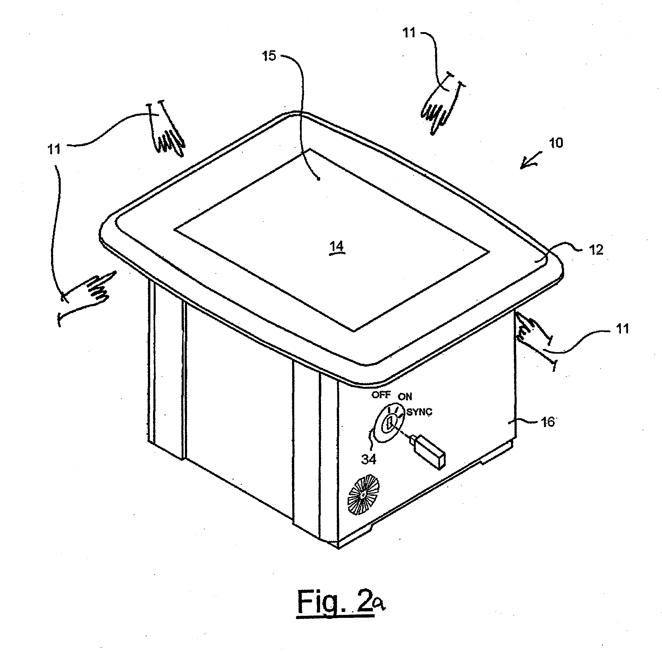
[0063]Turning now to FIGS. 2a and 2b, a perspective diagram of an interactive input system in the form of a touch table is shown and is generally identified by reference numeral 10. Touch table 10 comprises a table top 12 mounted atop a cabinet 16. In this embodiment, cabinet 16 sits atop wheels 18 that enable the touch table 10 to be easily moved from place to place in a classroom environment. Integrated into table top 12 is a coordinate input device in the form of a frustrated total internal refraction (FTIR) based touch panel 14 that enables detection and tracking of one or more pointers 11, such as fingers, pens, hands, cylinders, or other objects, applied thereto.

[0064]Cabinet 16 supports the table top 12 and touch panel 14, and houses ...


PUM


Abstract

A method for selecting a graphic widget displayed on a background of an interactive input system comprises tracking one or more touch points associated with the background, and in the event that one or more touch points coincide with a location of the graphic widget, associating the coinciding touch points with the graphic widget.

Description

[0001]This application is a continuation of U.S. patent application Ser. No. 12 / 240,919, filed Sep. 29, 2008, the entire contents of which are incorporated herein by reference.FIELD OF THE INVENTION [0002]The present invention relates generally to interactive input systems and in particular to a method for selecting and manipulating a graphic object in an interactive input system, and an interactive input system executing the method.BACKGROUND OF THE INVENTION [0003]Interactive input systems that allow users to inject input (i.e., digital ink, mouse events, etc.) into an application program using an active pointer (e.g., a pointer that emits light, sound or other signal), a passive pointer (e.g., a finger, cylinder or other suitable object) or other suitable input device such as for example, a mouse or trackball, are known. These interactive input systems include but are not limited to: touch systems comprising touch panels employing analog resistive or machine vision technology to ...

Claims


Application Information

Patent Timeline
IPC IPC(8): G06F3/041G09G5/00
CPCG06F3/0425G06F3/0488G06F2203/04808G06F2203/04109G06F3/04883
Inventor TSE, EDWARDROUNDING, KATHRYN
Owner SMART TECH INC (CA)
Why Eureka
Eureka Blog
Learn More