
Colorization method and apparatus

a colorization and colorization technology, applied in the field of colorization methods and apparatuses, can solve the problems of inability to perform tasks, and inability to accurately identify fuzzy or complex region boundaries of automatic segmentation algorithms

Inactive Publication Date: 2010-04-08
YISSUM RES DEV CO OF THE HEBREWUNIVERSITY OF JERUSALEM LTD
View PDF13 Cites 16 Cited by
  • Summary
  • Abstract
  • Description
  • Claims
  • Application Information

AI Technical Summary

Benefits of technology

[0025]If a segmentable region is not marked, then if it is surrounded by a region taking on a single color, it will also take on that color. If it is between two regions of different color it will usually either have an intermediate color or take on one of the neighboring colors, depending on the rates of change of the intensity between the color markings. The inventors have found that when the method of the invention is used, the colored image generally has all of the pixels colored, even when the markings are only made over some of the areas that would be segmented, were a segmentation algorithm employed. This makes colorization easier and results in a more pleasing end result.
[0035]In an embodiment of the invention, the controller generates a cost for each small region of the image, said cost being based on a difference between a color to be assigned to the small region and the color of neighboring pixels and a difference between the intensity of the small region and the neighboring pixels. Optionally, small regions consist of single pixels. Optionally, the controller finds a minimum cost for each of the small regions of the image and colors the image with colors according to said minimum cost. Optionally, the minimum cost is a global minimum cost considering all of the pixels being colored. Optionally, the generated cost increases with increasing color difference between nearby pixels. Optionally, the generated cost decreases with increasing intensity difference between neighboring pixels.
[0043]In an embodiment of the invention, the controller generates a cost for each small region of the image, said cost being based on a difference between a color to be assigned to the small region and the color of neighboring pixels and a difference between the original color of the small region and the neighboring pixels. Optionally the small regions consist of single pixels. Optionally, the controller finds a minimum cost for each of the small regions of the image and colors the image with colors according to said minimum cost. Optionally, the minimum cost is a global minimum cost considering all of the pixels being colored. Optionally, the generated cost increases with increasing color difference between nearby pixels. Optionally, the generated cost decreases with increasing intensity difference between neighboring pixels.
[0051]minimizing the cost without constraining the assigned colors to match the color markings, except at the markings themselves.
[0066]minimizing the cost for both images together without constraining the assigned colors to match the color markings, except at the markings themselves; and
[0072]minimizing the cost without constraining the assigned colors to match the color markings, except at the markings themselves.

Problems solved by technology

Neither of these tasks can be performed reliably in practice, and consequently colorization requires considerable user intervention and remains a tedious, time-consuming, and expensive task.
Unfortunately, even automatic segmentation algorithms often fail to correctly identify fuzzy or complex region boundaries, such as the boundary between a subject's hair and her face.
Thus, the artist is often left with the task of manually delineating complicated boundaries between regions.
Existing tracking algorithms typically fail to robustly track nonrigid regions, again requiring user intervention in the process.
While this technique has produced some impressive results, the artistic control over the outcome is quite indirect: the artist must find reference images containing the desired colors over regions with similar textures to those that she wishes to colorize.
It is also difficult to fine-tune the outcome selectively in problematic areas.
Also, the technique of Welsh et al. does not explicitly enforce spatial continuity of the colors, and in some images it may assign vastly different colors to neighboring pixels that have similar intensities.
In practice, it is not possible to distinguish bone voxels from blood vessel voxels with 100% accuracy; even two different doctors, attempting to do this task manually, will generally not agree on all voxels.

Method used


Image

  • Colorization method and apparatus
  • Colorization method and apparatus
  • Colorization method and apparatus

Examples


Embodiment Construction

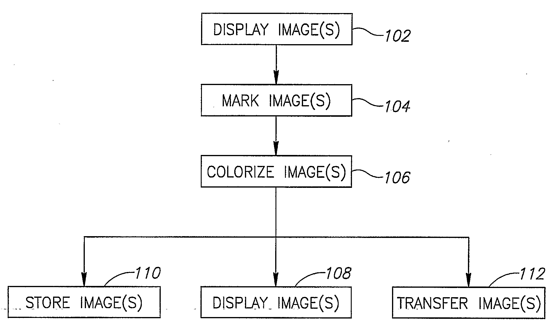
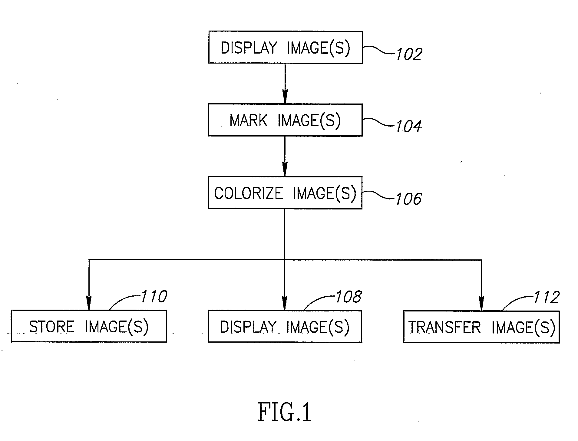
[0091]FIG. 1 is a flow chart 100 illustrating a method of colorization of an image, in accordance with an embodiment of the invention.

[0092]First, monochrome images are optionally displayed (102) on a display. Next places on the image are marked (104) with various colors. These markings are sometimes referred to as scribbles herein (even when they are only dots of color).

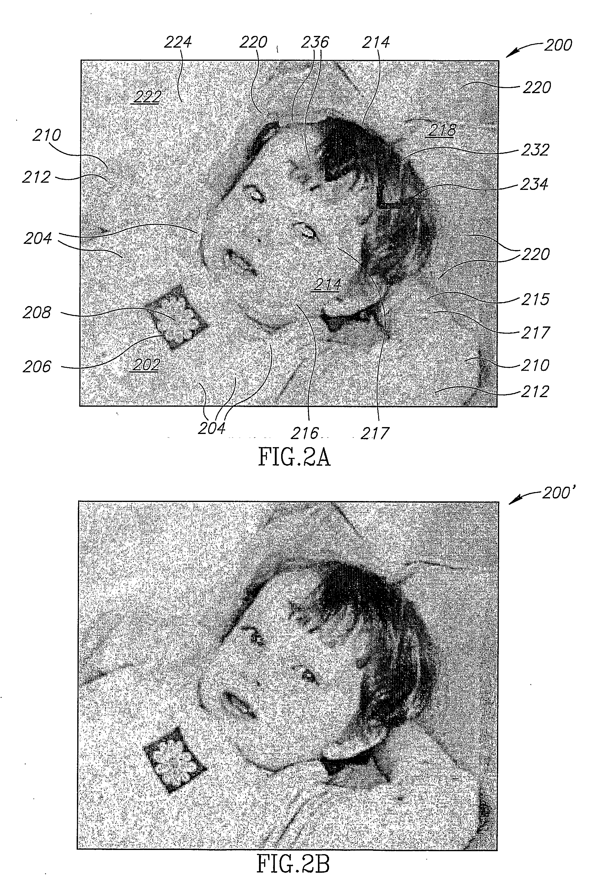
[0093]FIG. 2A illustrates an image 200 of a child lying on some pillows in which various places have been marked. For example, a child's shirt 202 has been marked with a yellow set of scribbles 204, the center of a daisy 206 has been marked with a red scribble 208, sleeves 210 of the shirt have been marked with a green scribble 212, face portions 214 and arm portions 215 have been marked with flesh color scribbles 216 and 217, having different hues, some hair 232 portions have been marked with dark brown scribbles 234 and others have been marked with lighter brown scribbles 236 to indicate highlights. Pillows 218 ha...


PUM


Abstract

A method for colorization of images is presented. The method comprises the following steps: Displaying an image (102); applying multiple color markings (at least two colors are different) to the displayed image (104); automatically coloring the image by applying a constrained optimization to a cost function that is responsive to the marked colors and the intensity differences of the neighborhoods of some of all of the pixels (106); the resultant image is subsequently stored (110), displayed (108), or transferred (112).

Description

RELATED APPLICATIONS AND SOURCES FOR COLOR PHOTOGRAPHS[0001]This application claims the benefit under 35 U.S.C. 119 (e) of provisional patent application Ser. No. 60 / 568,578, filed May 5, 2004. It was also published as “Colorization Using Optimization” in ACM Transactions on Graphics, August 2004. Both these documents are incorporated herein by reference.[0002]This application is being filed in a color version in the US Patent Office as a US Provisional Patent application on May 5, 2005 and in a monochrome version in the PCT on May 5, 2005, with color images provided for the search and examination authorities. In addition, the color images are posted at http: / / www.cs.huji.ac.il˜yweiss / Colorization / Patent.pdf for the reference of the reader. References to a particular color (in referring to color in the PCT version) should be understood in the context of the US provisional application and the web site, whose disclosure and figures are incorporated by reference into the PCT applicatio...

Claims


Application Information

Patent Timeline
IPC IPC(8): G09G5/02G06T7/00H04N9/43
CPCH04N9/43G06T11/001H04N1/465
Inventor LEVIN, ANATLISCHINSKI, DANIWEISS, YAIR
Owner YISSUM RES DEV CO OF THE HEBREWUNIVERSITY OF JERUSALEM LTD
Learn More