Transferred Medium

a technology of transfer media and transfer plate, which is applied in the direction of typewriters, instruments, thin material processing, etc., can solve the problems of easy damage of thin film, increased cost, and easy destruction of thin film provided at the front end of the tray

Inactive Publication Date: 2010-04-08
SEIKO EPSON CORP
View PDF7 Cites 10 Cited by
  • Summary
  • Abstract
  • Description
  • Claims
  • Application Information

AI Technical Summary

Benefits of technology

[0009]The present invention is contrived to solve the above-mentioned problems. It is an object of the present invention to provide a transferred medium, which can be nipped between a feed driving roller and a feed driven roller without releasing the feed driven roller, with low cost and without being easily destroyed and more particularly to provide a transferred medium having a structure for allowing the transferred medium to be easily nipped between a feed driving roller and a feed driven roller. The invention is as follows.

Problems solved by technology

However, in the structure employing the thin film, since a process of attaching the thin film thereto is required, there are problems in that increase in cost can be caused and the thin film can be easily damaged.
Specifically, when the tray is inserted into the printer, the thin film provided at the front end of the tray can be easily destroyed due to the forcible insertion of the tray into the printer.

Method used


Image

  • Transferred Medium
  • Transferred Medium
  • Transferred Medium

Examples


Embodiment Construction

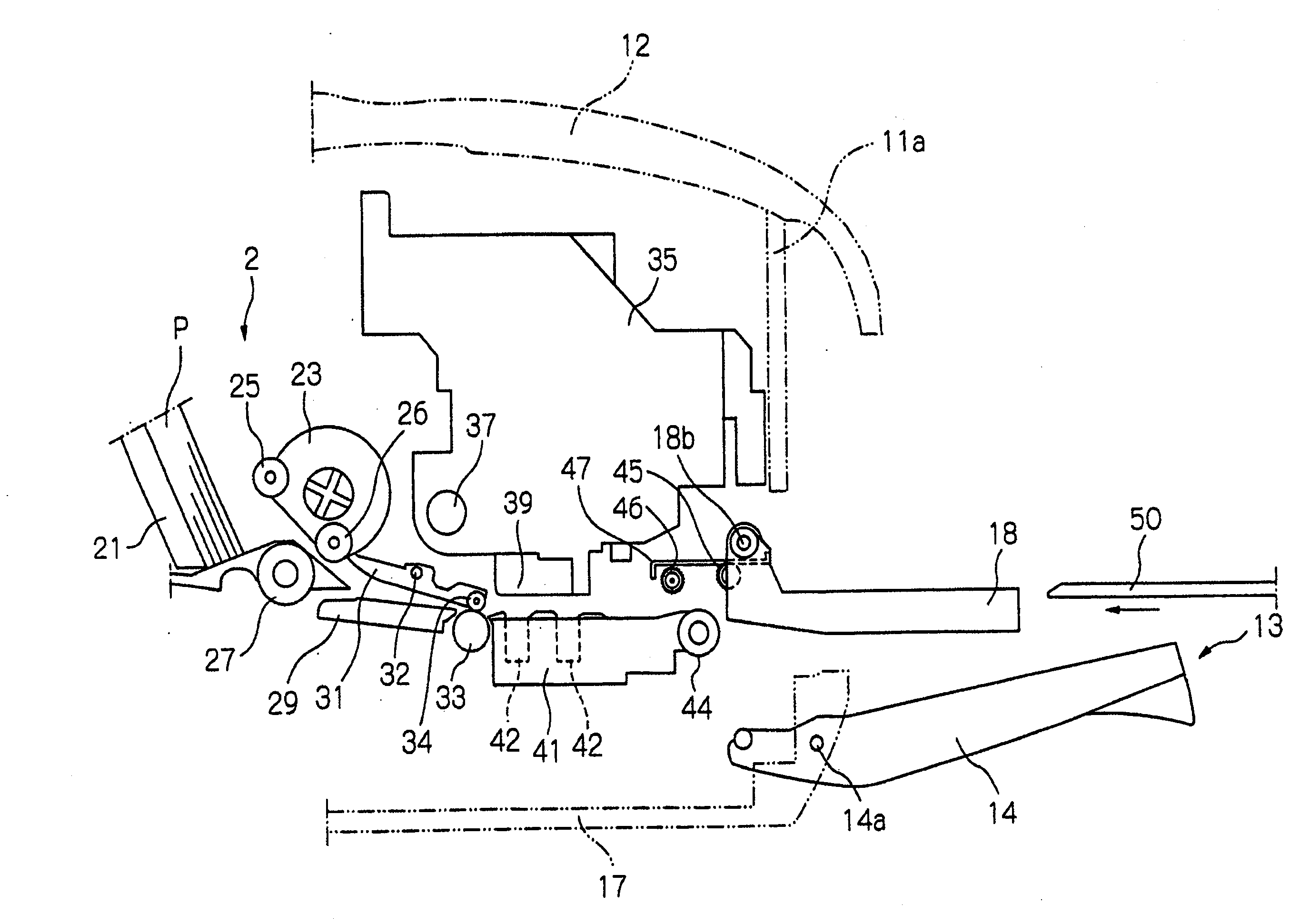
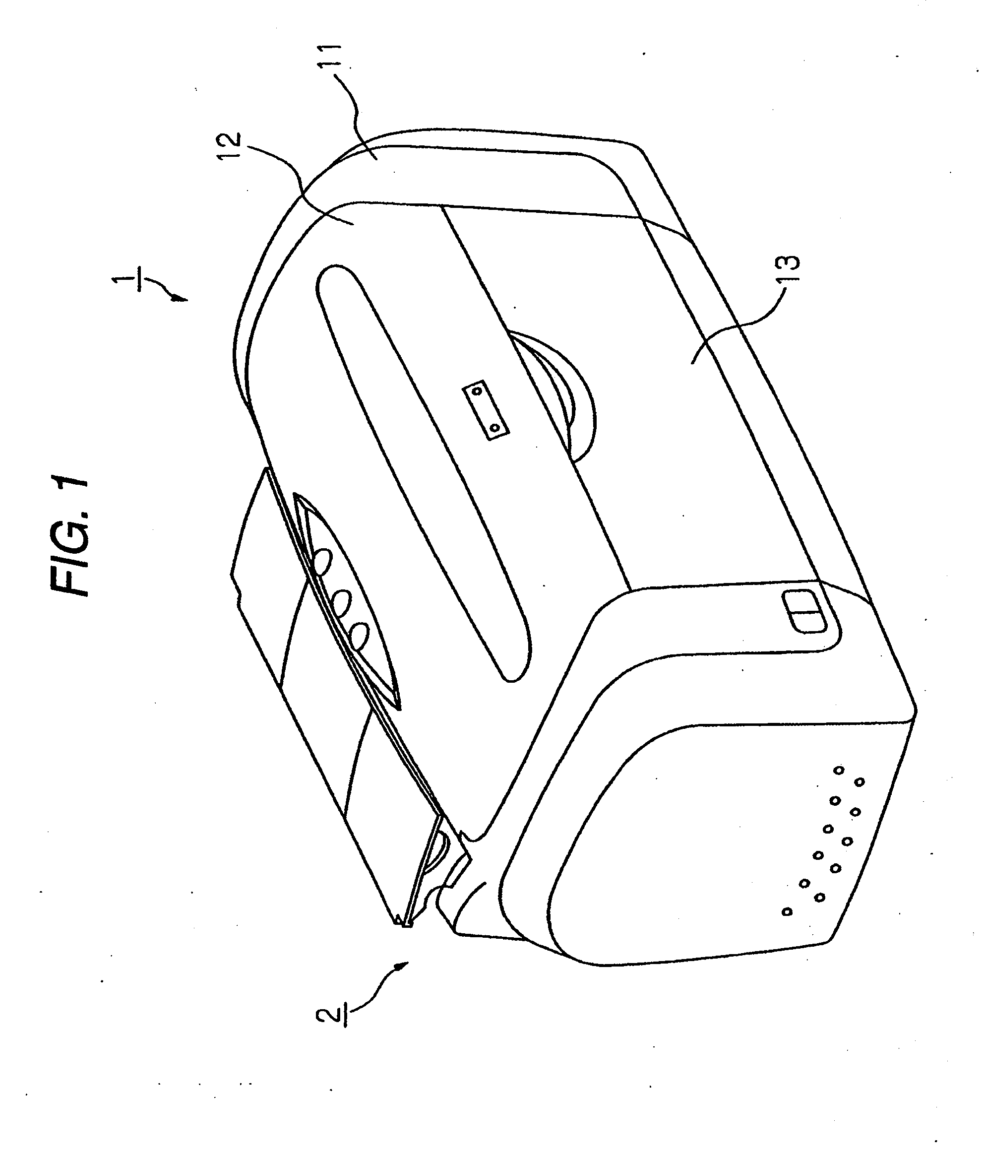
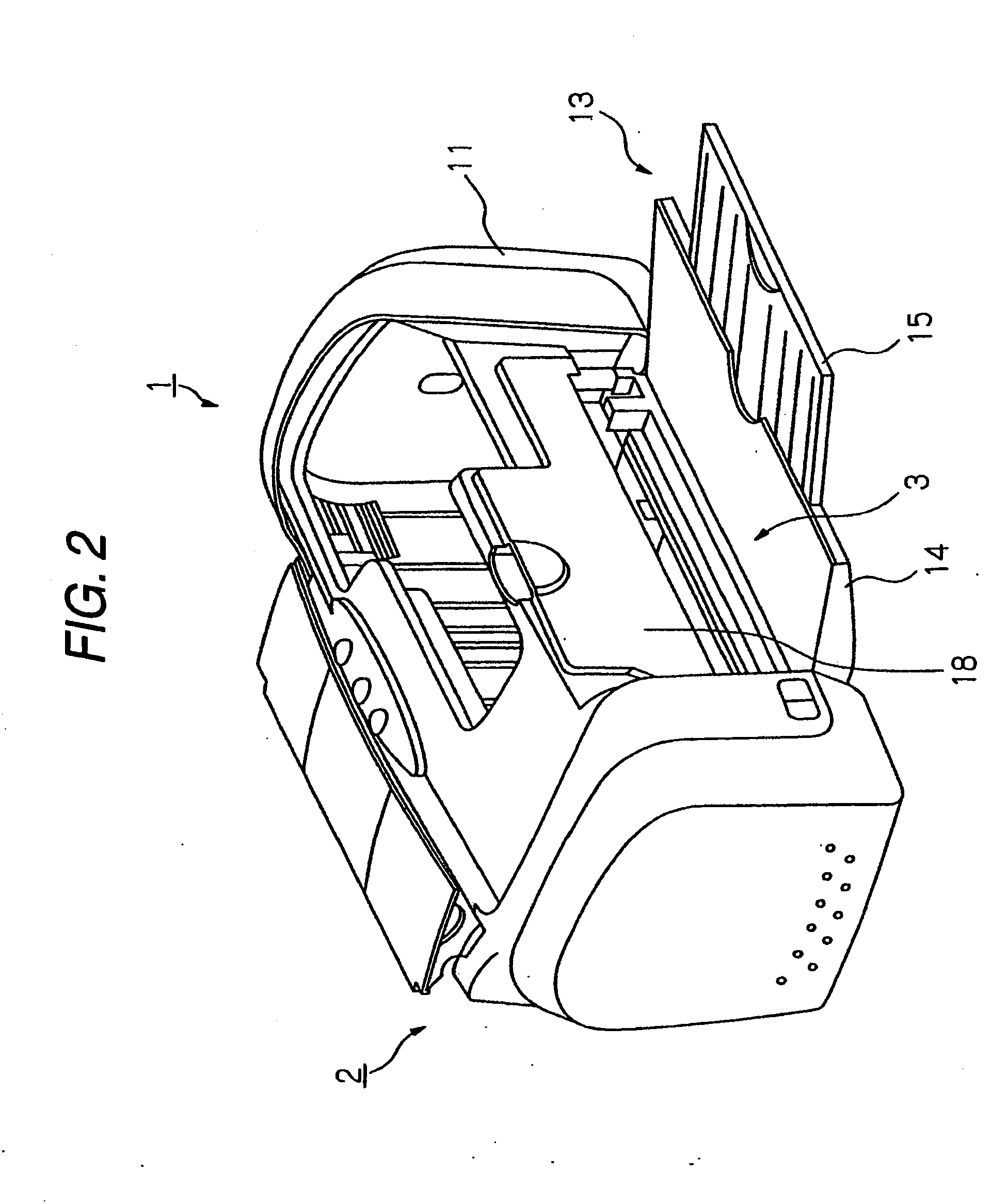
[0046]Hereinafter, exemplary embodiments of the present invention will be described with reference to the drawings. Here, an inkjet printer 1 (hereinafter, referred to as “printer”) as an example of a recording apparatus or a liquid jetting apparatus will be first schematically described with reference to FIGS. 1 to 5. FIGS. 1 to 3 are perspective views illustrating an appearance of the printer 1 and FIGS. 4 and 5 are side cross-sectional views of the printer 1. In the following description, the right side in FIGS. 4 and 5 (the front side of the printer) is referred to as the “downstream” of a paper feeding path and the left side (the rear side of the printer) is referred to as the “downstream” of the paper feeding path.

[0047]In FIG. 1, the printer 1 includes a feeding unit 2, in which a recording sheet (hereinafter, referred to as “paper P”) as an example of a “recording medium” or a “transferred medium” can be set with a tilted posture, at the rear portion thereof and a stacker 13...


PUM


Abstract

A transferred medium is provided. In one exemplary embodiment a transferred medium includes a projection part projected in a transferring direction. The projection part can be integrally formed at a front end of the transferred medium. The transferred medium can have a plate shape that can be nipped between a feed driving roller that is rotationally driven and a feed driven roller that is rotationally driven in contact with the feed driving roller. The transferred medium can also be configured to be transferred in the transferring direction with the rotation of the feed driving roller. Further, the transferred medium can include a plurality of the projection parts at its front end in a direction perpendicular to the transferring direction of the transferred medium with a predetermined pitch. Other embodiments of a transferred medium are also disclosed.

Description

RELATED APPLICATIONS[0001]This application claims priority as a divisional application to a utility application entitled “Transferred Medium” having Ser. No. 11 / 270,853, filed on Nov. 8, 2005, which claims priority to a Japanese Patent Application No. 2004-323430, filed on Nov. 8, 2004.BACKGROUND OF THE INVENTION[0002]1. Technical Field of the Invention[0003]The present invention relates to a transferred medium having a plate shape that can be nipped between a feed driving roller which rotates and a feed driven roller which rotates in dose contact with the feed driving roller and being transferred in a secondary scan direction in response to the rotation of the feed driving roller.[0004]2. Description of the Related Art[0005]Inkjet printers as an example of a recording apparatus or a liquid jetting apparatus may perform printing by ejecting ink droplets onto a label surface of an optical disk as a thin plate member such as a compact disk (CD) or a digital versatile disk (DVD). In su...

Claims


Application Information

Patent Timeline
Patent Type & Authority Applications(United States)
IPC IPC(8): B41J2/01
CPCB41J3/4071B41J13/103Y10T428/24479B41J11/58B41J13/106
Inventor TAKESHITA, SANSHIRO
Owner SEIKO EPSON CORP
Why Eureka
Try Eureka