
Light distribution panel having light distribution curves formed of multiple faces

a technology of light distribution panel and curve, which is applied in the direction of lighting and heating equipment, instruments, roads, etc., can solve the problems of poor road illumination effect, severe light pollution, and loss of brightness

Inactive Publication Date: 2010-04-08
TAIWAN NETWORK COMP & ELECTRONICS
View PDF7 Cites 20 Cited by
  • Summary
  • Abstract
  • Description
  • Claims
  • Application Information

AI Technical Summary

Benefits of technology

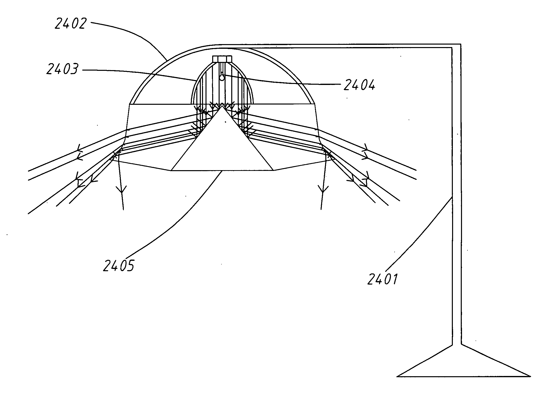
[0009]The present invention has been accomplished under the circumstances in view. It is one object of the present invention to provide a light distribution panel having light distribution curves formed of multiple faces, which is practical for use in a lamp, reflector for road line or solar energy collector panel, eliminating the drawbacks of the prior art designs. When used in a lamp or reflector for road line, the light distribution panel controls the angle of refraction or reflection of the major part of incident light, enabling light be evenly projected onto a predetermined illumination area.

Problems solved by technology

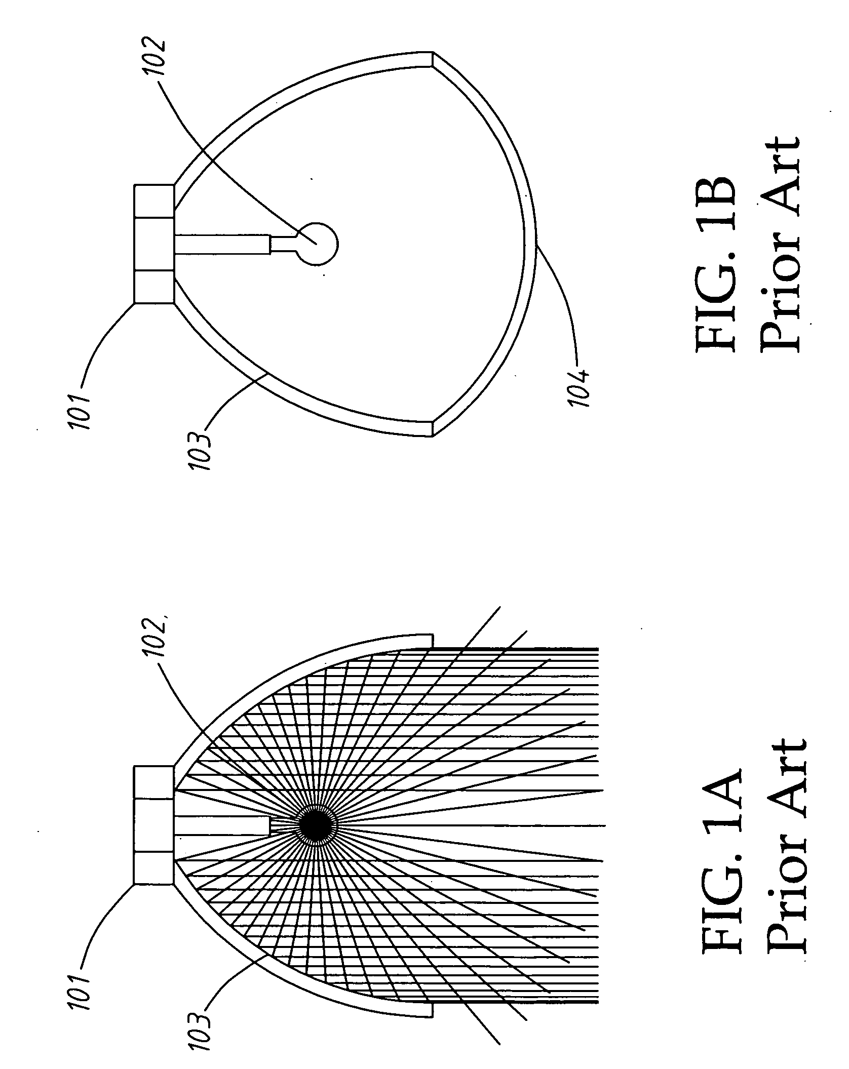
However, the frosted treatment of the transmitting covering 104 or the surface of the light source 102 results in a brightness loss.
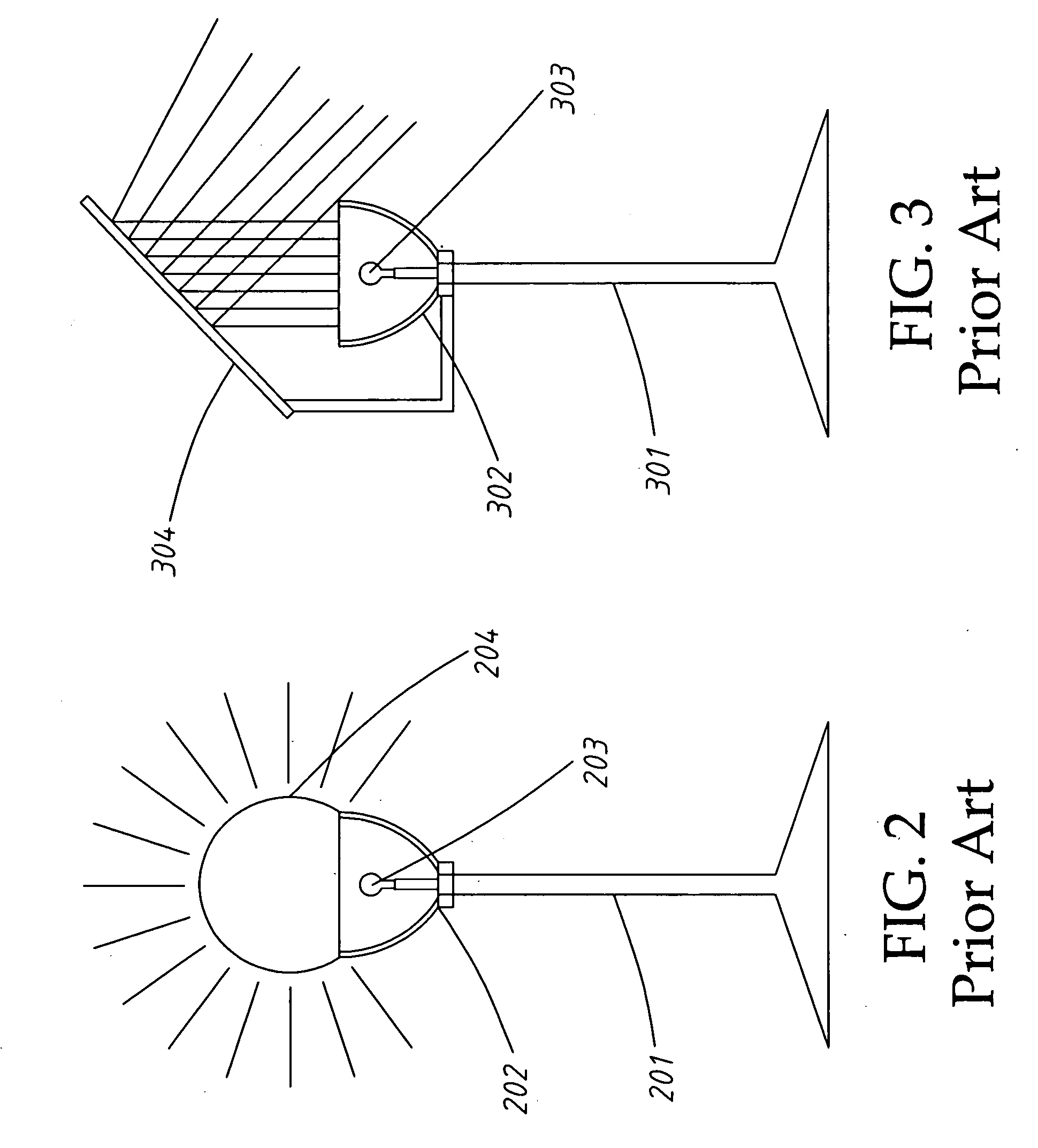
The light transmitting lampshade 204 allows light rays to go in different directions, providing a poor road illumination effect and causing a severe light pollution.
This design of street / park lamp has the drawback of limited illumination range.
However, when the fluorescent substance-coated plastic plate member is covered with dust, the reflection performance of the fluorescent substance-coated plastic plate member will be lowered or even disappeared.

Method used


Image

  • Light distribution panel having light distribution curves formed of multiple faces
  • Light distribution panel having light distribution curves formed of multiple faces
  • Light distribution panel having light distribution curves formed of multiple faces

Examples


Embodiment Construction

[0053]Referring to FIGS. 4, 4A and 4B, the drawings illustrate the structure and principle of the present invention and explain the operation of the present invention in controlling the movement of light rays.

[0054]Referring to FIG. 4, a light distribution panel 401 is shown having multiple faces. When two incident light rays 402 fall upon one face 403 of the light distribution panel 401 at one same angle and go to another face 404 after refraction, the contained angle between the incident light rays 402 and the normal line 405 is smaller than the critical angle of the light distribution panel. Subject to refraction law, the light rays are refracted out of the light distribution panel.

[0055]When changing the angle of the face 404 shown in FIG. 4 to the angle of the face 407 shown in FIG. 4A, the contained angle between the incident light rays 402 and the normal line 408 is greater than the critical angle of the light distribution panel. Subject to reflection law (the angle of incide...


PUM


Abstract

Practical for use to make a road divider / reflector or a solar collector, a light distribution panel is disclosed to include four faces that can be planar or arched faces and constitute a light distribution curve to control the moving direction of light. When used in a lamp, light is evenly distributed onto the expected illumination area, avoiding formation of Gauss distribution and providing broad area illumination. When used as a road reflector, the light distribution panel provides excellent driving safety effect. When used in a solar collector system, the light distribution panel collects a wide range of incident light.

Description

BACKGROUND OF THE INVENTION[0001]1. Field of the Invention[0002]The present invention relates to light distribution technology and more particularly, to a light distribution panel having light distribution curves formed of multiple faces and designed subject to the principles of optical refraction and reflection of critical angle of the medium. The light distribution panel is suitable for use in lamps, road lines and reflectors, and solar energy collection. When used for illumination, the light distribution panel minimizes brightness loss, provides even and soft luminance, saves energy, and avoids light pollution. When used in road line, the light distribution gives a prominent indication. When used in a solar collector system, the light distribution panel lowers the cost of the solar collector panel.[0003]2. Description of the Related Art[0004]Regular lamps include two types, one for indoor application and the other for outdoor application. A lamp for indoor application, as shown i...

Claims


Application Information

Patent Timeline
Patent Type & Authority Applications(United States)
IPC IPC(8): F21V7/00F21V5/00E01F9/615F21Y101/00
CPCF21S6/005F21S8/08F21V5/00F21V7/0008F21V7/0091G02B19/0033F24J2/08Y02E10/44G02B19/0042G02B19/0047G02B19/0028F24J2/06Y02B20/72F24S23/00F24S23/30
Inventor CHUANG, PING-HAN
Owner TAIWAN NETWORK COMP & ELECTRONICS
Learn More