Sealing strap

a technology of sealing straps and straps, applied in the field of sealing straps, can solve the problems of poor waterproof effect of zip fasteners of this design, and achieve the effect of excellent tensile strength and waterproof

Inactive Publication Date: 2016-07-14
TAN FU HSING
View PDF0 Cites 53 Cited by
  • Summary
  • Abstract
  • Description
  • Claims
  • Application Information

AI Technical Summary

Benefits of technology

[0005]The present invention has been accomplished under the circumstances in view. It is therefore the main object of the present invention to provide a sealing strap, which is practical for use in a waterproof product to achieve excellent tensile strength and waterproof effects.
[0006]To achieve this and other objects of the present invention, a sealing strip of the invention comprises a first strap body, a second strap body, and a zipper slider. The first strap body comprises aa first base portion, a first lining and a second lining extending along one lateral side of the first base portion at different elevations, a first interlocking series of teeth extended from the first lining and a male engaging member with a male engagement portion extended from the second lining. The second strap body comprises a second base portion, a third lining and a fourth lining extending along one lateral side of the second base portion, a second interlocking series of teeth extended from the third lining, and a female engaging member with a female engagement portion extended from the fourth lining. The zipper slider is movable to force the first interlocking series of teeth into engagement with the second interlocking series of teeth and the male engagement portion of the male engaging member into engagement with the female engagement portion of the female engaging member to achieve excellent tensile strength and waterproof effects.

Problems solved by technology

However, the waterproof effect of a zip fastener of this design is poor.

Method used


Image

  • Sealing strap
  • Sealing strap
  • Sealing strap

Examples


Embodiment Construction

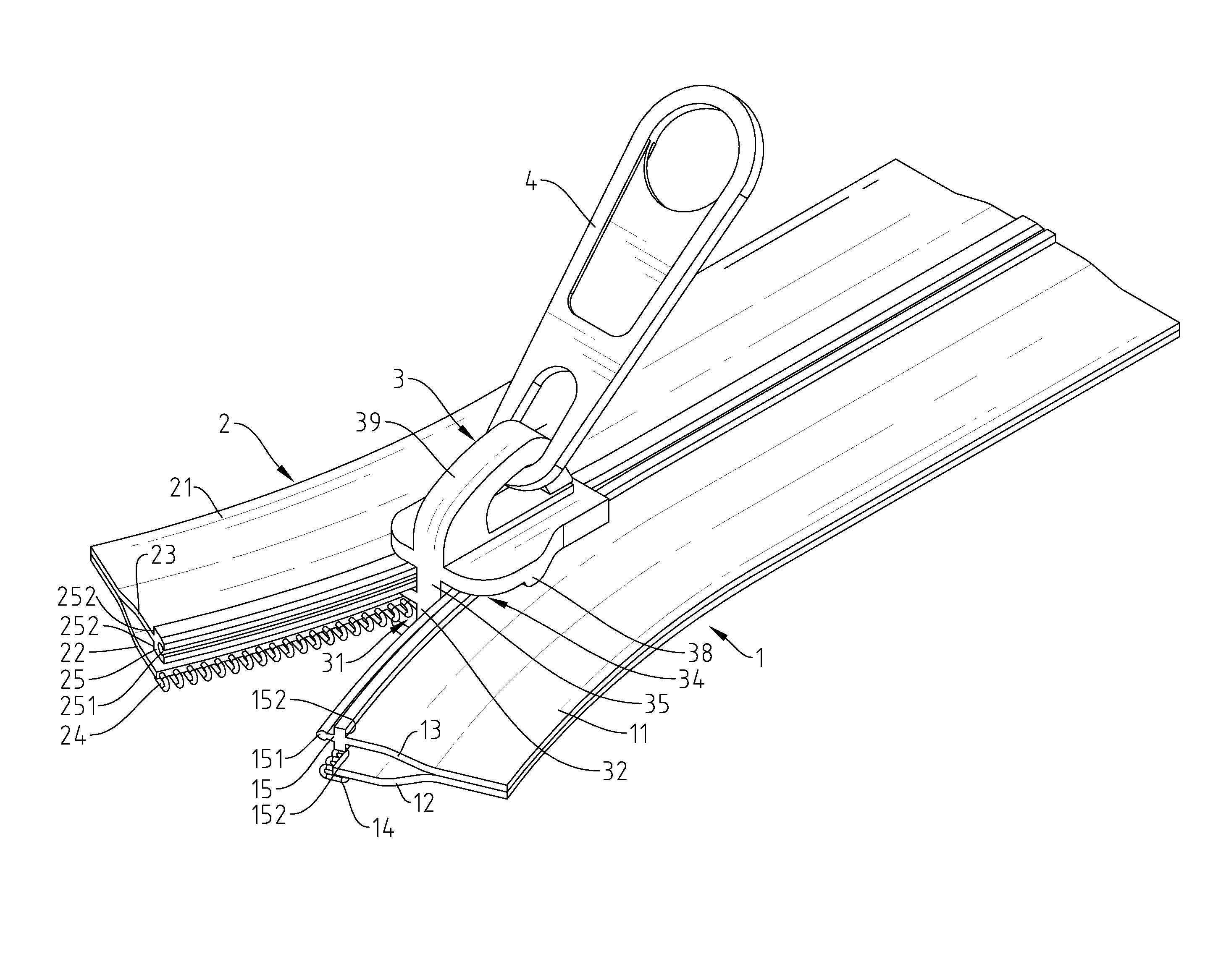
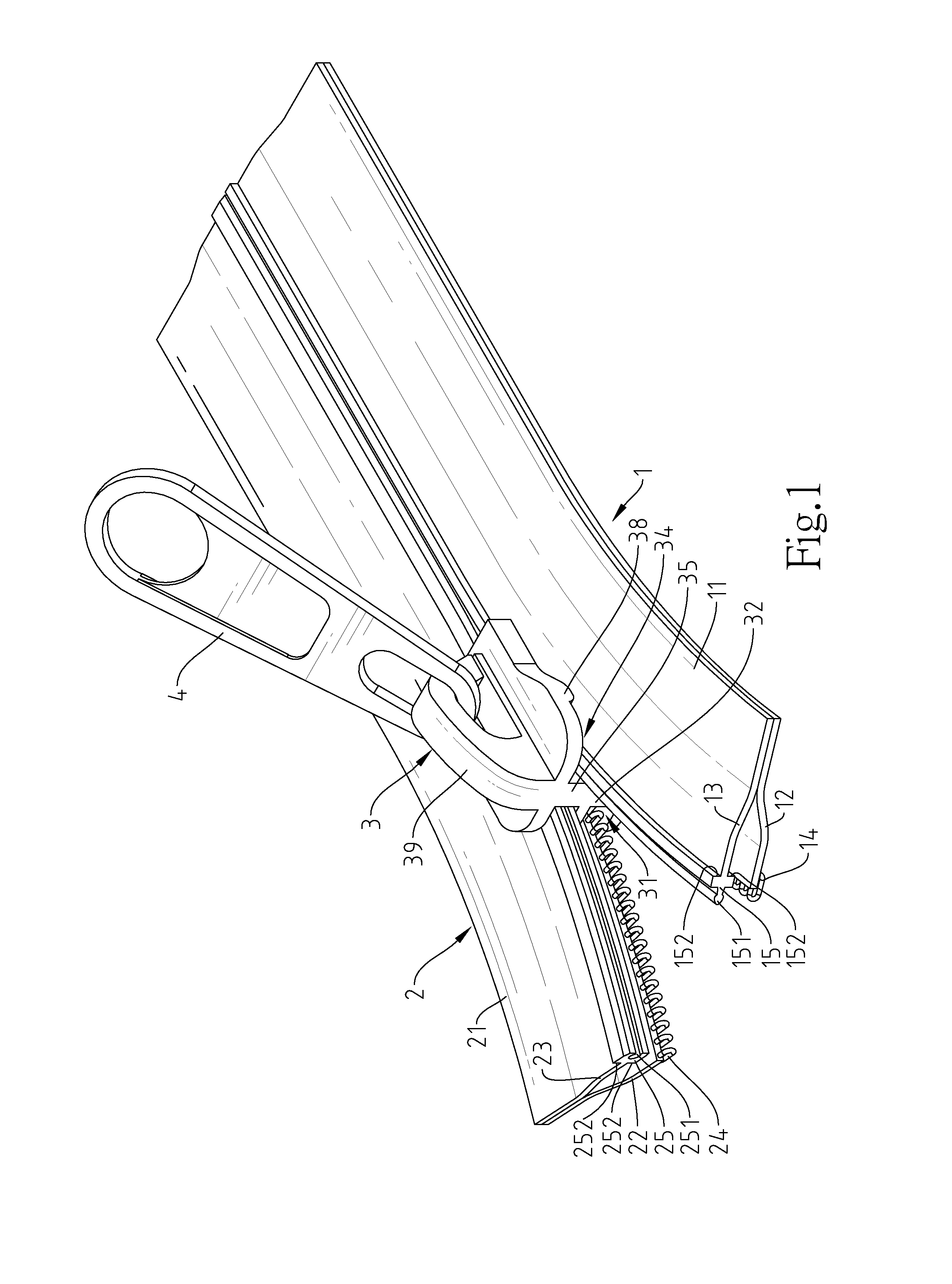
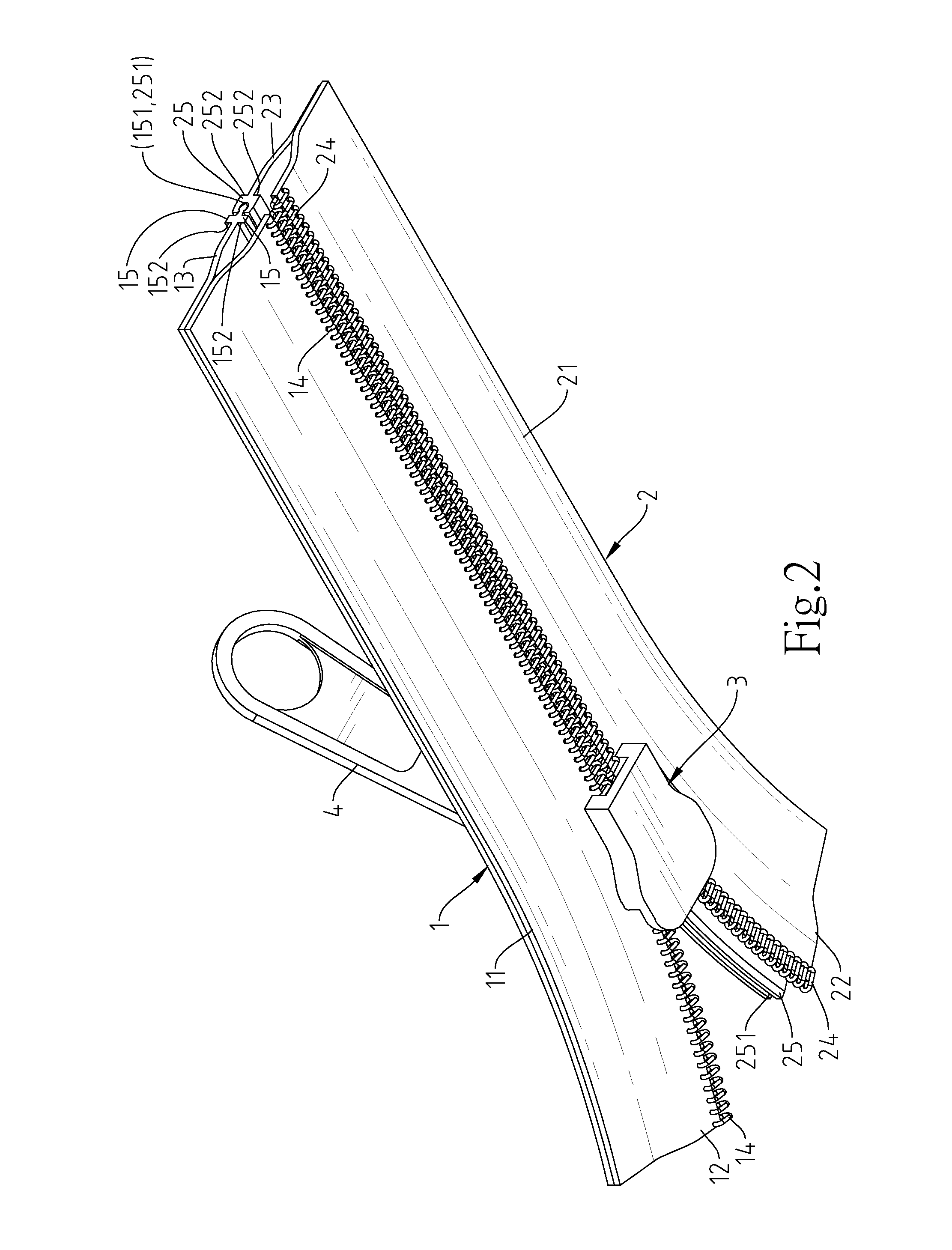
[0014]Referring to FIGS. 1-7, a sealing strap in accordance with the present invention is shown. The sealing strap comprises a first strap body 1, a second strap body 2 and a zipper slider 3.

[0015]The first strap body 1 comprises a first base portion 11, a first lining 12 and a second lining 13 respectively extended from one lateral side of the first base portion 11 at different elevations, a first interlocking series of teeth 14 longitudinally arranged along one lateral side of the first lining 12 opposite to the first base portion 11, and a male engaging member 15 longitduinally extending along one laterail side of the second lining 13 opposite to the first base portion 11. The male engaging member 15 is formed integral with one lateral side of the second lining 13, comprising a male engagement portion 151 longitudinally extending along one lateral side thereof opposite to the second lining 13, and two first vertical bearing walls 152 respectively abutted to the opposing top and b...


PUM


Abstract

A sealing strap includes a first strap body including a first base portion, a first lining, a second lining, a first interlocking series of teeth extended from the first lining and a male engaging member with a male engagement portion extended from the second lining, a second strap body including a second base portion, a third lining, a fourth lining, a second interlocking series of teeth extended from the third lining, and a female engaging member with a female engagement portion extended from the fourth lining, and a zipper slider movable to force the first interlocking series of teeth into engagement with the second interlocking series of teeth and the male engagement portion of the male engaging member into engagement with the female engagement portion of the female engaging member to achieve excellent tensile strength and waterproof effects.

Description

BACKGROUND OF THE INVENTION[0001]1. Field of the Invention[0002]The present invention relates to sealing technology and more particularly, to a sealing strap operable by a zipper slider to force a first interlocking series of teeth into engagement with a second interlocking series of teeth and a male engagement portion of a male engaging member into engagement with a female engagement portion of a female engaging member, achieving excellent tensile strength and waterproof effects.[0003]2. Description of the Related Art[0004]A regular zip fastener generally comprises two zipper tapes, two interlocking series of teeth respectively longitudinally stitched to the zipper tapes, and a zipper slider movable to force the two interlocking series of teeth into engagement with each other, achieving a good tensile strength. However, the waterproof effect of a zip fastener of this design is poor. If a zip fastener of this design is used in a waterproof product (waterproof bag, raincoat, etc.), t...

Claims


Application Information

Patent Timeline
Patent Type & Authority Applications(United States)
IPC IPC(8): A44B19/32A44B19/16A44B19/26
CPCA44B19/32A44B19/16A44B19/26A44B19/262A44B19/12A44B19/22
Inventor TAN, FU-HSING
Owner TAN FU HSING
Why Eureka
Try Eureka