
Fixing device and image forming apparatus incorporating same

a technology of fixing device and image forming apparatus, which is applied in the direction of electrographic process apparatus, instruments, optics, etc., can solve the problems of degrading image quality, and affecting the image quality of the sheet p

Inactive Publication Date: 2010-04-08
RICOH KK
View PDF12 Cites 12 Cited by
  • Summary
  • Abstract
  • Description
  • Claims
  • Application Information

AI Technical Summary

Problems solved by technology

The problem is that thereafter, when the curved sheet P is transported to the fixing device A, the sheet P might jam and wrinkle because the sheet P does not enter the fixing nip N103 properly.
However, when the guide member 700 is located on the side of an unfixed-image surface, that is, a surface of the sheet P on which the unfixed toner image is formed (left side surface in FIG. 19), the guide member 700 contacts the unfixed-image surface, disturbing the image T on the sheet P and thus degrading image quality.
In this case, there are concerns that the image on the trailing-edge portion of the sheet P might be disturbed and the image quality might be degraded.
Moreover, the known fixing devices do not include a specific mechanism, to prevent the trailing-edge of the curved sheet P from contacting the guide member.

Method used


Image

  • Fixing device and image forming apparatus incorporating same
  • Fixing device and image forming apparatus incorporating same
  • Fixing device and image forming apparatus incorporating same

Examples


second embodiment

[0140]In FIG. 15, a fixing device 50 includes a fixing roller 52 inside which a heater 51 is provided, and a pressure roller 53 that contacts the fixing roller 52 with pressure. The fixing device 50 does not include a fixing belt. Instead, the fixing device 50 uses the fixing roller 52 as a rotary fixing member. The fixing roller 52 is rotated by a driving member, not shown, and the pressure roller 53 rotates as the fixing roller 52 rotates.

[0141]The toner image T on the sheet P is fixed by passing the sheet P on which an unfixed toner image T is formed through a fixing nip N305 formed between the fixing roller 52 and the pressure roller 53.

third embodiment

[0142]In FIG. 16, a fixing device 60 includes a fixing roller 62 inside which a heater 61 is provided, and a pressure belt 63 that is a seamless belt to press the fixing roller 62. The pressure belt serves as a rotary pressure member. The pressure belt 63 is pressed against the fixing roller 62 by a pressure pad 64, and the pressure belt 63 is rotated at a speed similar to the speed at which the fixing roller 62 rotates.

[0143]The toner image T on the sheet P is fixed by passing the sheet P on which an unfixed toner image T is formed through a fixing nip N306 formed between the fixing roller 62 and the pressure belt 63.

fourth embodiment

[0144]In FIG. 17, a fixing device 70 includes a heating roller 72 inside which a heater 71 is provided, a fixing pad 73, a fixing belt 74 extended around the fixing pad 73 and the heating roller 72, and a pressure roller 76 that includes a heater 75 and contacts the fixing belt 74 in a portion facing the fixing pad 73. As the pressure roller 76 rotates, the fixing belt 74 is rotated.

[0145]The toner image T on the sheet P is fixed by passing the sheet P on which an unfixed toner image T is formed through a fixing nip N3.7 formed between the fixing belt 74 and the pressure roller 76.


PUM


Abstract

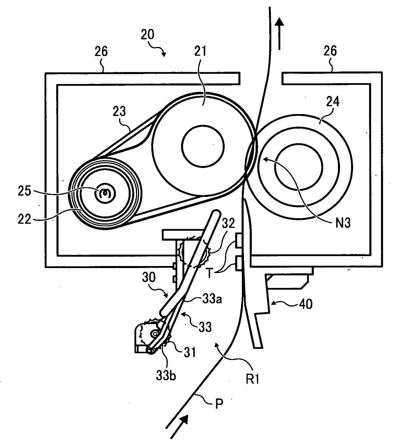
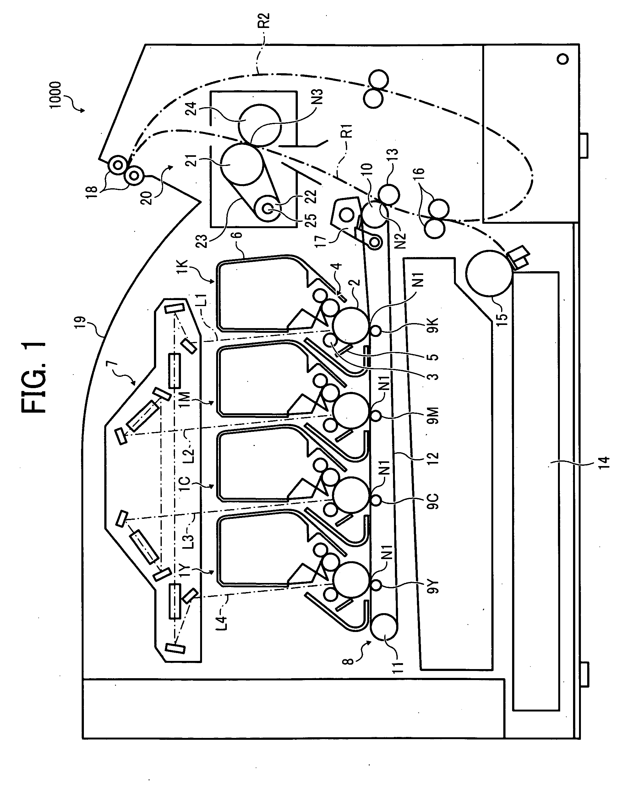
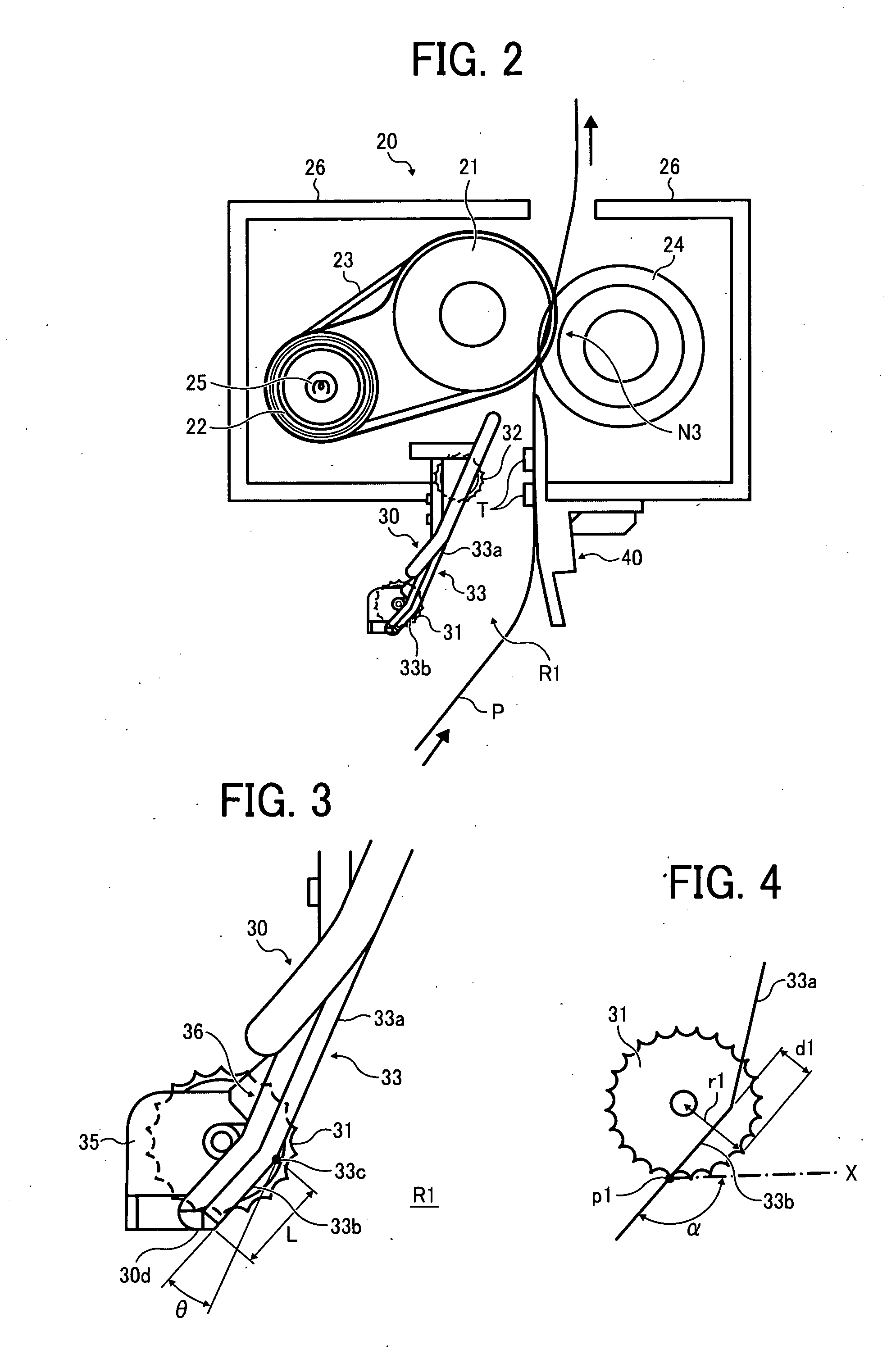
A fixing device includes a fixing nip and a guide member to guide a recording medium transported through a recording media transport pathway to the fixing nip, disposed upstream from the fixing nip in a direction in which the recording medium is transported and facing an unfixed-image side of the recording media. The guide member includes a guide face, the guide face including a first guide face and a second guide face located where at least a trailing-edge of the recording medium approaches the guide member as the recording medium is transported through the recording media transport pathway and which is inclined with respect to the first guide face away from the recording media transport pathway, and a first spur rotatably provided on the guide member and projecting into the recording media transport pathway from a connection portion between the first guide face and the second guide face.

Description

CROSS-REFERENCE TO RELATED APPLICATIONS[0001]This patent specification claims priority from Japanese Patent Application No. 2008-257222, filed on Oct. 2, 2008 in the Japan Patent Office, which is hereby incorporated by reference herein in its entirety.BACKGROUND OF THE INVENTION[0002]1. Field of the Invention[0003]The present invention relates to a fixing device to fix images on recording media, and an image forming apparatus employing the fixing device.[0004]2. Discussion of the Background[0005]In image forming apparatuses, such as printers, facsimile machines, copiers, plotters, or multi-functional peripherals having several of the foregoing functions, fixing devices that fix a toner image on a recording medium such as a paper sheet by heating and pressing the toner image onto the sheet are widely used.[0006]With reference to FIG. 19, configuration of such a fixing device A is described below. As shown in FIG. 19, the fixing device A includes a rotatable fixing roller 100, a heate...

Claims


Application Information

Patent Timeline
IPC IPC(8): G03G15/20
CPCG03G15/2028G03G15/2085
Inventor SAKAYA, KOHTA
Owner RICOH KK
Learn More