Combination-cell foam floating island

a foam island and cell technology, applied in the field of floating islands, can solve the problems of fragile methods of providing buoyancy, and achieve the effects of reducing manufacturing costs, preventing soil loss, and providing buoyancy

Inactive Publication Date: 2010-04-15
FOUNTAINHEAD
View PDF43 Cites 7 Cited by
  • Summary
  • Abstract
  • Description
  • Claims
  • Application Information

AI Technical Summary

Benefits of technology

[0006]The purpose of the invention is to provide an economical floating island. Some embodiments of the invention comprise a material (combination-cell thermoplastic foam) that has not been used in the background art. This material has several beneficial properties that require the use of multiple materials in the background art. The material provides buoyancy via the closed cells, water wicking and water adsorption via the open cells; it is penetrable by plant roots and resistant to chemical and sunlight degradation. When used under pockets of bedding soil, it prevents loss of soil while supporting root growth and providing buoyancy. The formulation of the combination-cell foam can be varied so as to produce a variety of foam products from the same resin stock, thereby reducing manufacturing costs.
[0007]Some embodiments of the invention are specifically designed to maximize the use of scrap materials, thereby reducing production costs and also converting waste products into environmentally beneficial products. Fastening devices have been improved over the background art to be more economical, stronger, and more efficient.
[0008]Utilization of combination open / close celled foam as a comprehensive one-material floating island solution allows for simplified, less expensive mass production. This, in combination with features like enhanced ultraviolet (UV) light protection, provides for a higher quality, more consistent product.

Problems solved by technology

This method of providing buoyancy tends to be fragile (e.g., subject to failure by impact from boats and pressure from freezing ice) and expensive.

Method used


Image

  • Combination-cell foam floating island
  • Combination-cell foam floating island
  • Combination-cell foam floating island

Examples


Embodiment Construction

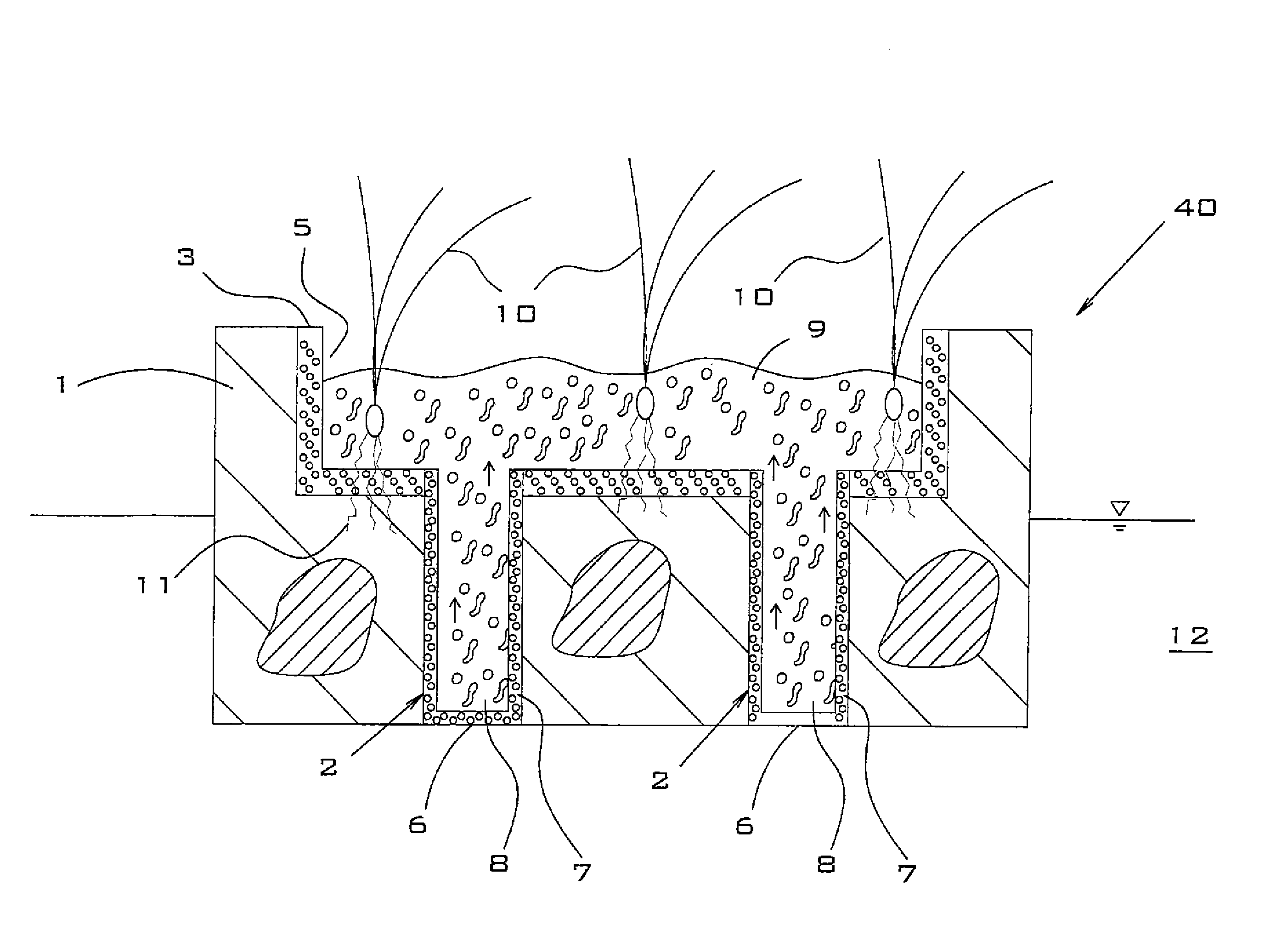
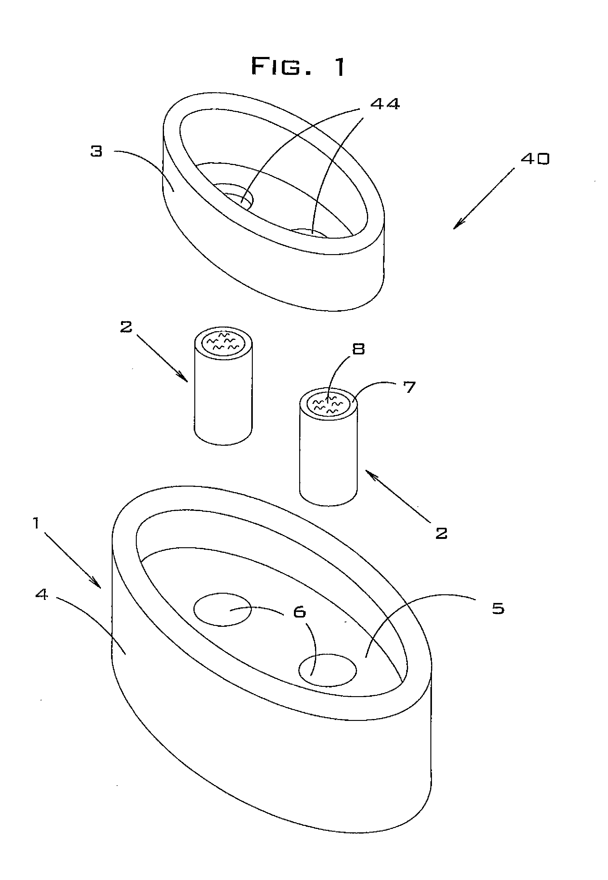
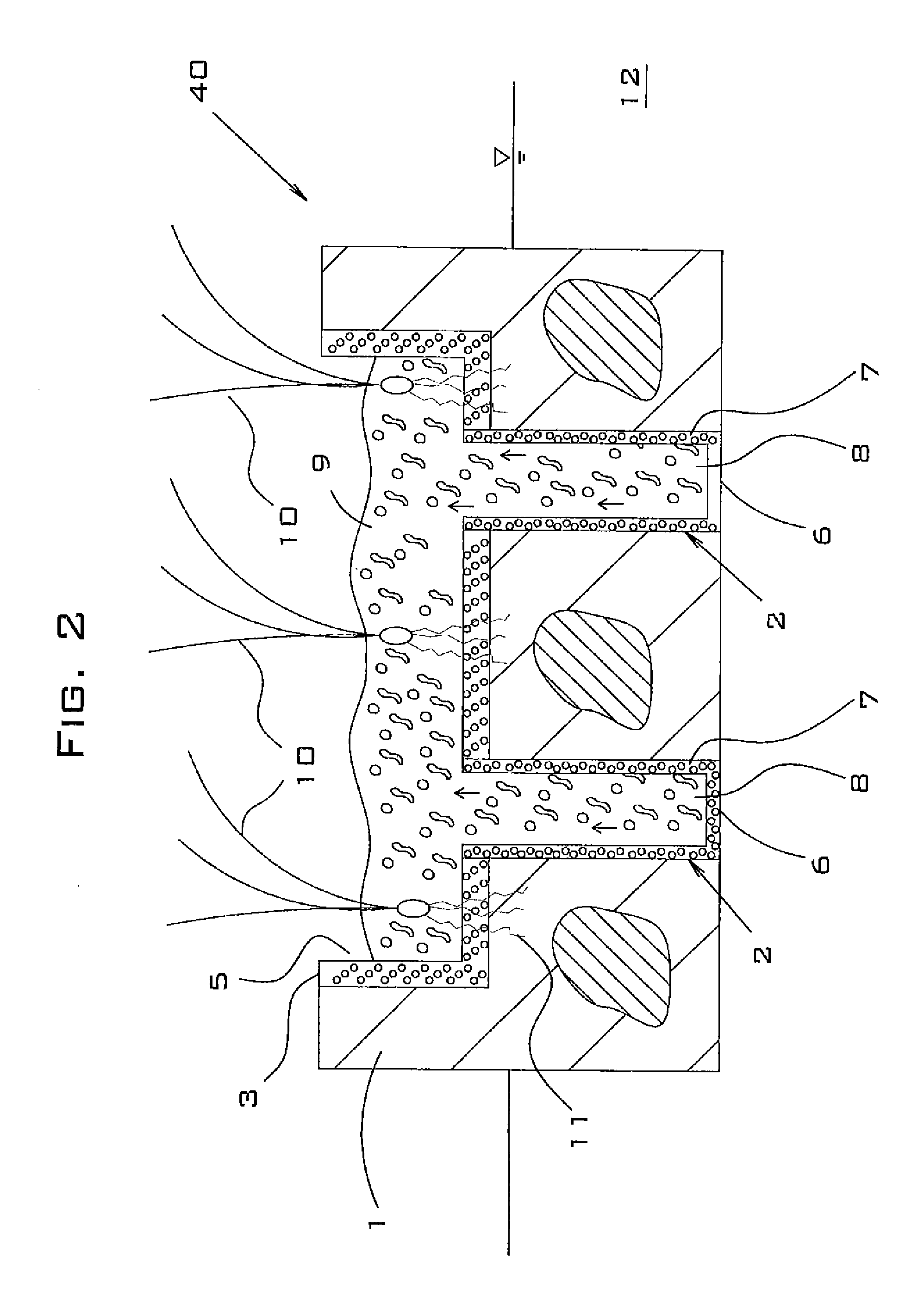
[0090]Referring to FIG. 1, a preferred embodiment of floating island 40 is illustrated that comprises island body 1, wicking cups 2 and shaped liner 3 for preventing the loss of growth medium. Island body 1 is preferably further comprised of a nonwoven thermosetting or thermoplastic fiber matrix 4 that has central cavity 5 and bottom cutout holes 6. Wicking cups 2 are preferably comprised of outer layer 7 and central portion 8. Central portion 8 is preferably filled with growth medium that has been formulated to have wicking ability.

[0091]An example of a suitable growth medium is BIOMIX® manufactured by Floating Island International of Shepherd, Mont. BIOMIX is a mixture comprising a hydrophilic polymer foam and a plurality of organic materials such as peat and bark.

[0092]Outer layer 7 is preferably comprised of thermoplastic polymer foam that has been manufactured specifically to have a combination of open cell and closed cell pore spaces within the polymer material (to comprise a ...


PUM


Abstract

A floating island comprising a combination-cell thermoplastic foam. In a preferred embodiment, the invention is a floating island comprising: an island body comprising at least a first portion that comprises a combination-cell thermoplastic foam and having a cavity; and a bedding material that is disposed in said cavity; wherein said combination-cell thermoplastic foam is buoyant in water and permeable to gas and water. In another embodiment, the invention is a floating island comprising: an island body comprising a first matrix layer, a second matrix layer and a third matrix layer; and a gas-trapping insert that is disposed between two of said layers.

Description

CROSS-REFERENCE TO RELATED APPLICATION[0001]This application is a divisional of U.S. patent application Ser. No. 11 / 927,318 filed on Oct. 29, 2007. The contents of that application are incorporated herein by reference.BACKGROUND OF THE INVENTION[0002]This invention relates to floating islands. In particular, the invention relates to combination-cell foam floating islands.[0003]The background art is characterized by U.S. Pat. Nos. 5,224,292; 5,528,856; 5,766,474; 5,980,738; 6,086,755; and 6,555,219 and U.S. Patent Application Nos. 2003 / 0051398; 2003 / 0208954; 2005 / 0183331; the disclosures of which patents and patent applications are incorporated by reference as if fully set forth herein.[0004]Background art floating planters have four major deficiencies that are overcome in preferred embodiments of the present invention. Some background art planters are predominantly covered by materials that prevent or restrict plant growth. For example, the invention described by Tepper (U.S. Pat. N...

Claims


Application Information

Patent Timeline
Patent Type & Authority Applications(United States)
IPC IPC(8): A01G9/02
CPCA01G9/00A01G9/28
Inventor KANIA, BRUCE G.STEWART, FRANK M.
Owner FOUNTAINHEAD
Why Eureka
Try Eureka