
Solar Array Mounting System with Universal Clamp

a solar array and mounting system technology, applied in the direction of heat collector mounting/support, solar thermal energy generation, etc., can solve the problems of increasing the cost of photovoltaic solar panels with other means of energy generation, and damage to panels, support structures,

Active Publication Date: 2010-04-15
COROSOLAR LLC
View PDF17 Cites 108 Cited by
  • Summary
  • Abstract
  • Description
  • Claims
  • Application Information

AI Technical Summary

Benefits of technology

[0012]The elongated slot may be sized to accommodate solar panel mounting holes which are located in a band approximately 0.5″ to 1.25″ from an edge of a solar panel frame. Alternatively, the elongated slot may be sized to accommodate solar panel mounting holes which are located in a band approximate...

Problems solved by technology

With the continual rise in conventional energy costs, photovoltaic solar panels (“PV panels”) are increasingly becoming cost competitive with other means of energy generation.
However, such large solar arrays require a sufficiently strong support structure to support not only the weight of the array, but to also provide sufficient resistance to wind forces.
Tightly spaced panels effectively form a large surface area, which could result in damage to the panels, the support structure, or both, under strong wind conditions.
For mounting hardware manufactures, this may require the design of many different mounting brackets, increasing the costs associated with tooling and inventory control.
If a PV panel is defective and / or damaged and needs to be replaced, it is difficult to only remove a single panel.
This type of mounting system also often requires extensive on-site placement, measurement, and adjustment on the part of the system installers.
Moreover, these clips do not utilize the manufacturers' mounting holes, and therefore the installations may not meet the manufacturers' installation guidelines and / or invalidate warranties.

Method used


Image

  • Solar Array Mounting System with Universal Clamp
  • Solar Array Mounting System with Universal Clamp
  • Solar Array Mounting System with Universal Clamp

Examples


Embodiment Construction

[0052]The following description is provided to enable any person skilled in the art to make and use the invention and sets forth the best modes contemplated by the inventor for carrying out the invention. Various modifications, however, will remain readily apparent to those skilled in the art. Any and all such modifications, equivalents and alternatives are intended to fall within the spirit and scope of the present invention.

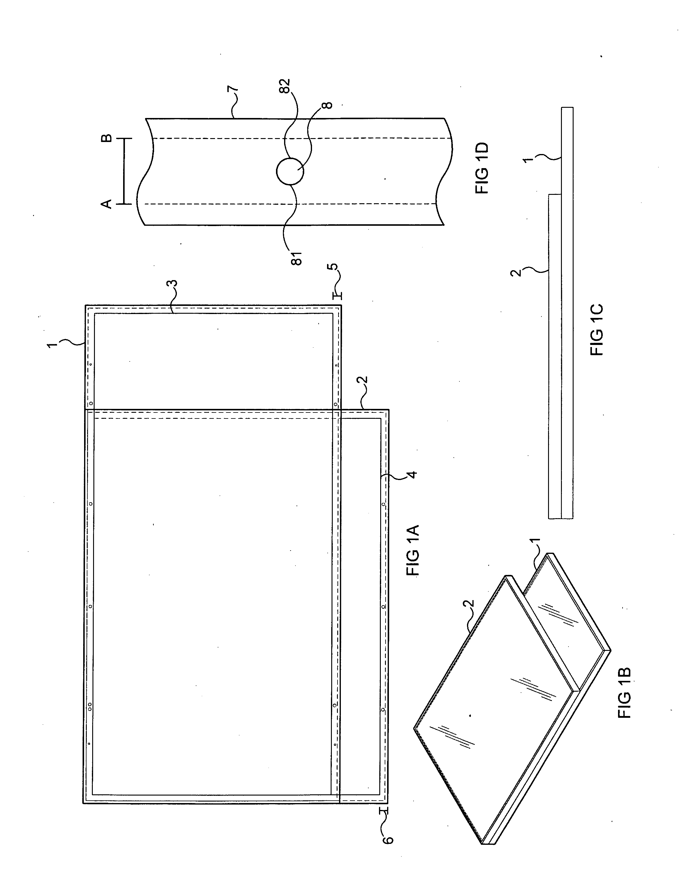
[0053]As described above, photovoltaic solar panels may vary in size and shape. As shown in FIGS. 1A-1C, some panels are generally rectangular (1), while others may have a more square aspect ratio (2). Even among similarly shaped panels, though, the lengths and widths of the panels vary, especially between different manufacturers.

[0054]Most flat photovoltaic solar panels typically comprise an aluminum frame around the panel to allow the panel to be mounted on a support structure. The frame has a folded “lip” on the back side of the panel having pre-drilled hole...


PUM


Abstract

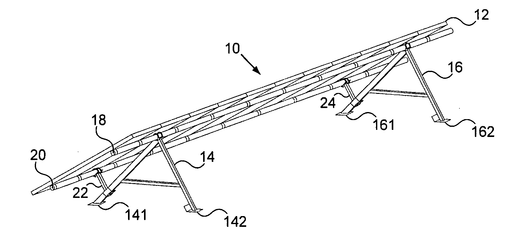
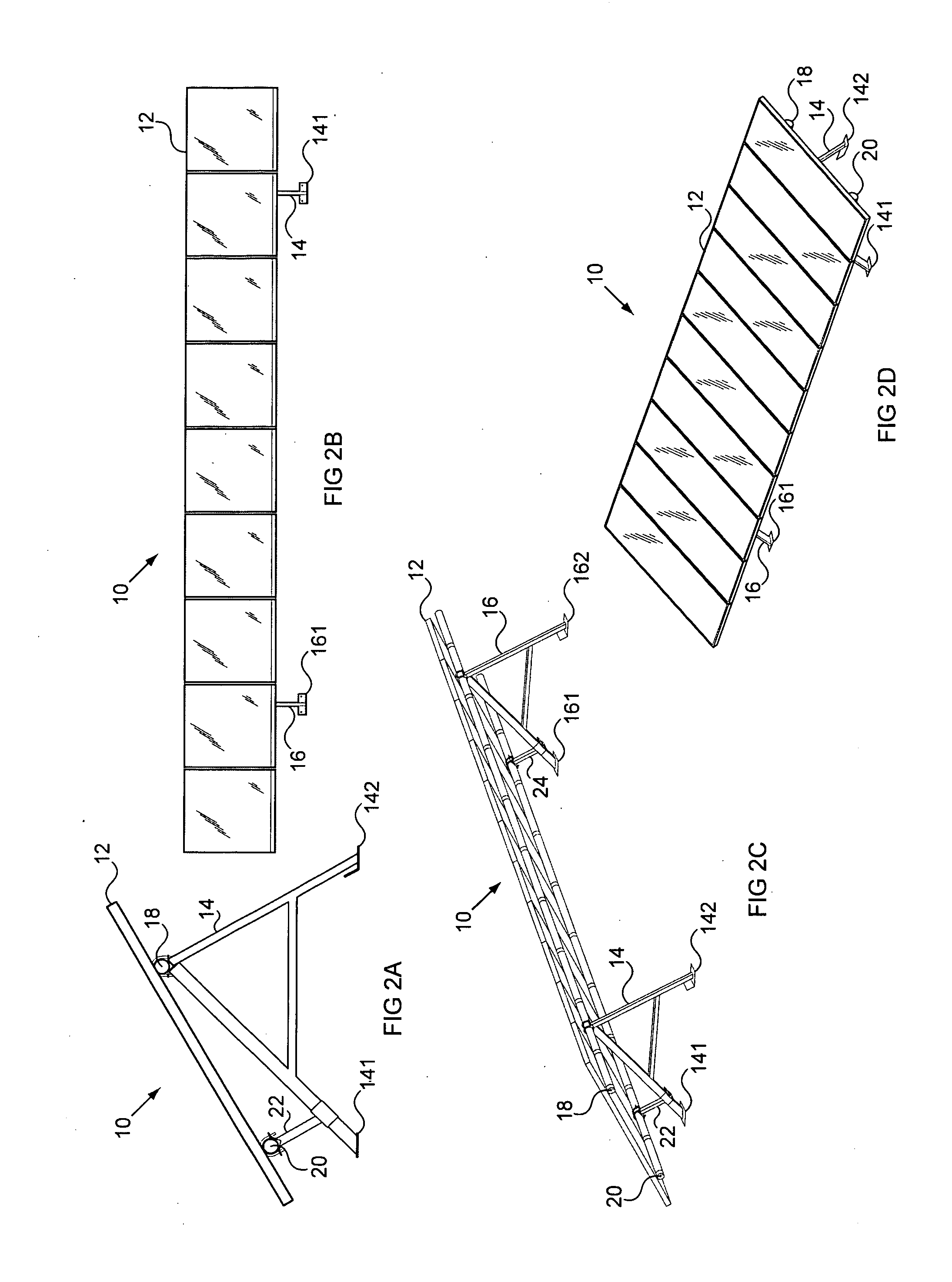
A mounting system for photovoltaic solar panels providing support for different sized panels, and / or panels having mounting holes located in different locations. A universal panel clamp includes at least one elongated hole or slot to attach to a mounting hole on a solar panel frame. A clamp is attached to an upper hole, and a second clamp is attached to a lower mounting hole. The upper clamps are attached to an upper lateral support member, and the lower clamps are attached to a lower lateral support member. This assembly may be supported by A-shaped support members having adjustable tilt arms, or posts with specially configured brackets.

Description

BACKGROUND OF THE INVENTION[0001]1. Field of the Invention[0002]The present invention relates generally to a system for mounting and installing photovoltaic solar panels, and more particularly, to a mounting support system that can support photovoltaic solar panels manufactured by different vendors.[0003]2. Description of the Related Art[0004]With the continual rise in conventional energy costs, photovoltaic solar panels (“PV panels”) are increasingly becoming cost competitive with other means of energy generation. These PV panels are being installed in sites of high energy usage such as on commercial building rooftops, in industrial open areas, and even on reclaimed wasteland. These energy systems, or power plants, vary in size but can cover many thousands of square feet on a building rooftop and many acres of land when installed on the ground. Ground mounted systems are especially attractive for large commercial power-generating installations, and locations with large available op...

Claims


Application Information

Patent Timeline
IPC IPC(8): F24J2/46
CPCF16B9/023F24J2/5211F24J2/5232F24J2/5254F24J2/5258F24J2/5264Y10T24/44043H01L31/0422Y02E10/47F16B2/12Y02B10/12Y02E10/50H02S20/00F24J2002/5216F24S25/12F24S25/20F24S25/632F24S25/636F24S25/65F24S25/70F24S2025/802H02S20/10H02S20/24Y02B10/10Y02B10/20H01L31/042
Inventor SEERY, MARTINMIROS, ROBERT H.J.
Owner COROSOLAR LLC
Learn More