Shale Shakers with Selective Series/Parallel Flow Path Conversion

Active Publication Date: 2010-04-15
NAT OILWELL VARCO LP
View PDF100 Cites 76 Cited by
  • Summary
  • Abstract
  • Description
  • Claims
  • Application Information

AI Technical Summary

Benefits of technology

[0025]In addition to the specific objects stated below for at least certain preferred embodiments of the invention, other objects and purposes will be readily apparent to one of skill in this art who has the benefit of this invention's teachings and disclosures. It is, therefore, an

Problems solved by technology

Often circulation is lost at some specific depth where the formation is “weak”, and that the fracture extends horizontally away from the borehole.
Screening the drilling mud for removal of undesired particulate matter can also result in removal of the lost circulation material and, therefore, require continuous introduction of new lost

Method used


Image

  • Shale Shakers with Selective Series/Parallel Flow Path Conversion
  • Shale Shakers with Selective Series/Parallel Flow Path Conversion
  • Shale Shakers with Selective Series/Parallel Flow Path Conversion

Examples


Embodiment Construction

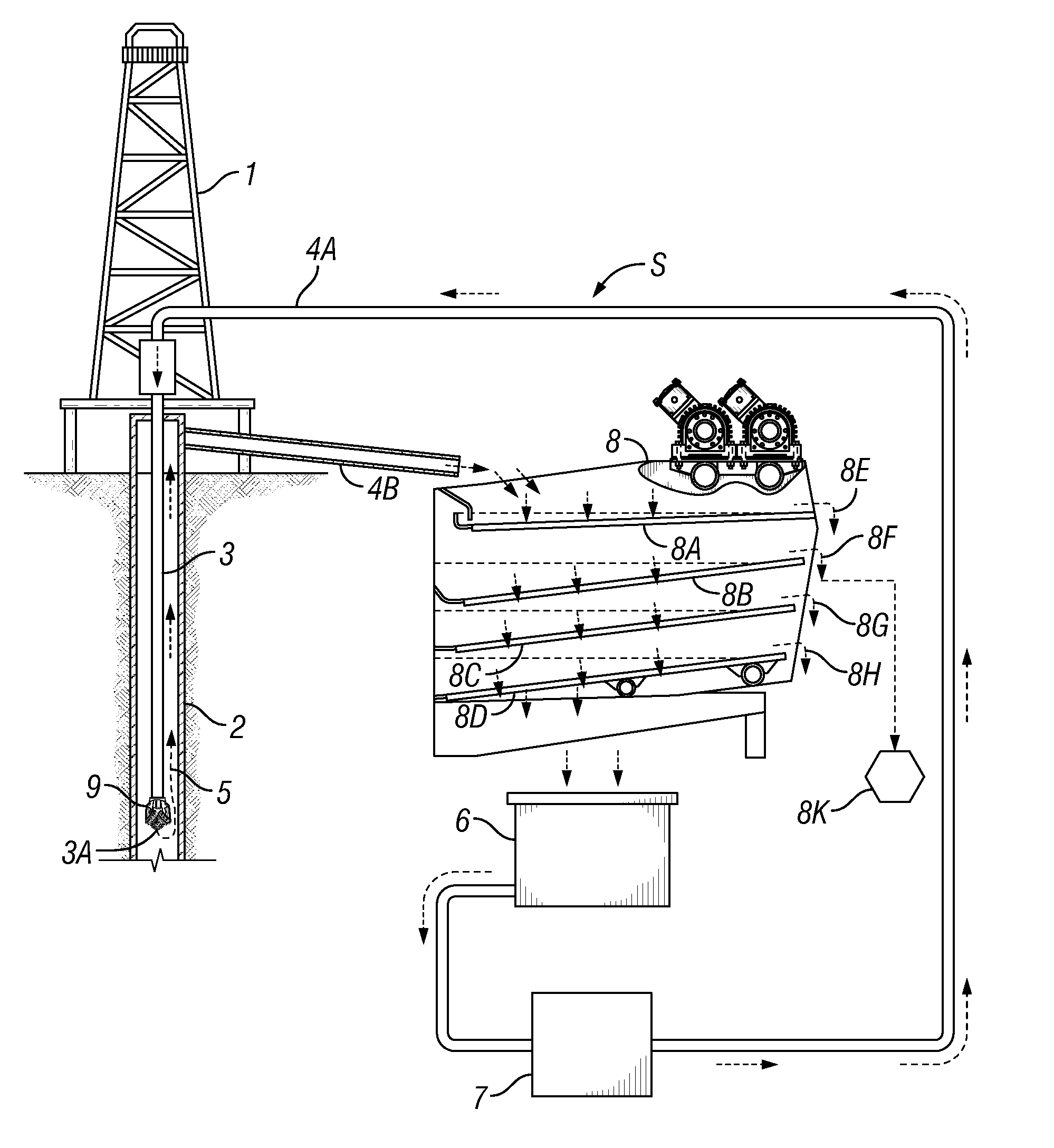
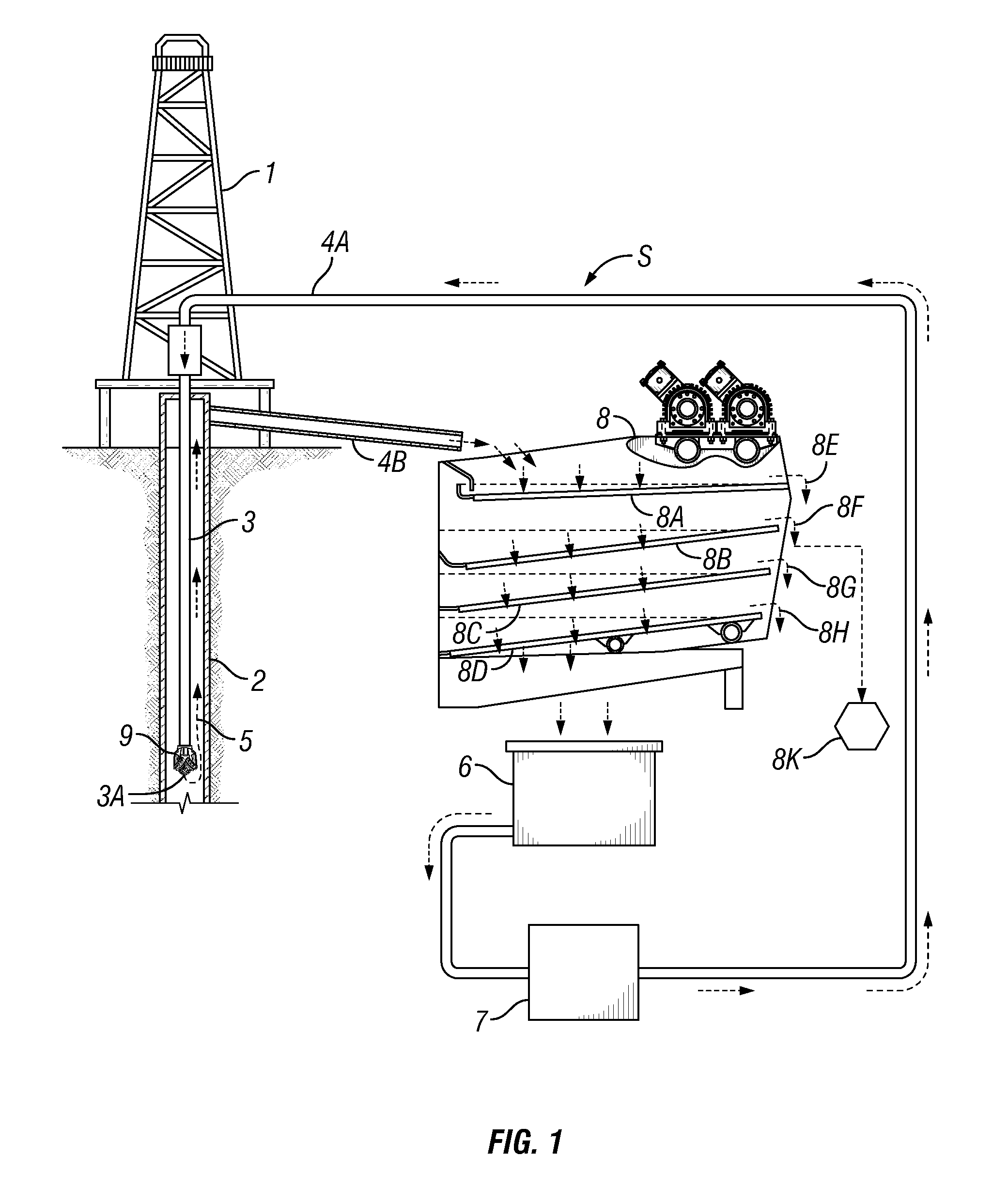
[0094]FIG. 1 illustrates a system S according to the present invention which includes a derrick 1 that extends vertically over a wellbore 2. A tubular work string 3 extends into the wellbore 2, and extends from the earth's surface to a desired depth within the wellbore. A flow line 4a is connected to the tubular work string 3. A flow line 4b is connected to annular space 5 formed between the outer surface of tubular work string 3 and the inner surface of wellbore 2.

[0095]Drilling fluid (or “mud”) for the system in a mud pit 6 is circulated through the overall mud system via a mud pump 7. During typical drilling operations, fluid is pumped into the tubular work string 3 by the mud pump 7 through the flow line 4a, circulated out a bottom end 3a of the tubular work string 3 (e.g., but not limited to, out from a drill bit 9), up an annulus 5 of the wellbore 2, and out of the annulus 5 via the flow line 4b.

[0096]Spent (or used) fluid mud exiting the wellbore annulus 5 through the flow li...


PUM

PropertyMeasurementUnit
Flow rateaaaaaaaaaa
Sizeaaaaaaaaaa

Abstract

Methods and systems are disclosed employing a shale shaker for processing a mixture of drilling fluid and solids with multiple screen assemblies and conversion apparatus for switching flow to the screen assemblies between series flow and parallel flow; and in one aspect, a screen or screens for screening lost circulation material.

Description

CROSS-REFERENCE TO RELATED APPLICATIONS[0001]This Application is a continuation-in-part of U.S. application Ser. No. 12 / 287,709 filed on Oct. 10, 2008 entitled “Systems and Methods For the Recovery of Lost Circulation and Similar Material” incorporated by reference herein for all it discloses.BACKGROUND OF THE INVENTION[0002]1. Field of the Invention[0003]The present invention is directed to drilling fluid processing systems; shale shakers; to methods for using these things; and, in certain particular aspects, to shale shakers with structure for converting shaker fluid flow paths from series to parallel, and vice versa.[0004]2. Description of the Related Art[0005]In the oil and gas industries, shale shakers use screens to treat drilling fluid contaminated with undesirable solids. Typically such apparatuses have a basket, deck, or other screen holding or mounting structure mounted in or over a receiving receptacle or tank and vibrating apparatus for vibrating one or more screens. Mat...

Claims


Application Information

Patent Timeline
IPC IPC(8): E21B21/06B07B1/28B01D33/03
CPCB01D33/0376B07B1/28B07B1/46B07B13/16E21B21/065B07B2201/04B07B2230/01B07B13/18B01D33/41
Inventor BURNETT, GEORGE ALEXANDER
Owner NAT OILWELL VARCO LP
Why Eureka
Try Eureka