Behind-the-ear hearing aid whose microphone is set in an entrance of ear canal

Inactive Publication Date: 2010-04-15
PANASONIC CORP
View PDF18 Cites 63 Cited by
  • Summary
  • Abstract
  • Description
  • Claims
  • Application Information

AI Technical Summary

Benefits of technology

[0039]The present invention provides a behind-the-ear hearing aid in which a microphone is disposed in the entrance of an ear canal, thereby makes it possible to handle the sound coming from the sound source as input sound on which a frequency characteristic of the pinna is reflected. As a consequence, there can be provided a behind-the-ear hearing aid that makes it easy for a hearing aid wearer to estimate the position of a sound source in a vertical direction as well as in a horizontal direction; particularly, in a front-back direction.

Problems solved by technology

Recently hearing aid users tend to prefer a BTE hearing aid to an ITE type, because the BTE hearing aid is compact and unobtrusive when the user put it on a behind a pinna.

Method used


Image

  • Behind-the-ear hearing aid whose microphone is set in an entrance of ear canal
  • Behind-the-ear hearing aid whose microphone is set in an entrance of ear canal
  • Behind-the-ear hearing aid whose microphone is set in an entrance of ear canal

Examples


first embodiment

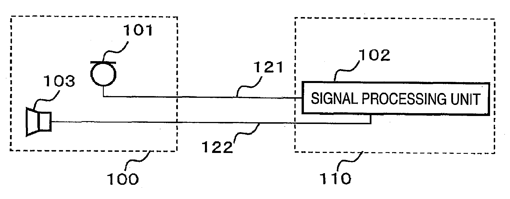
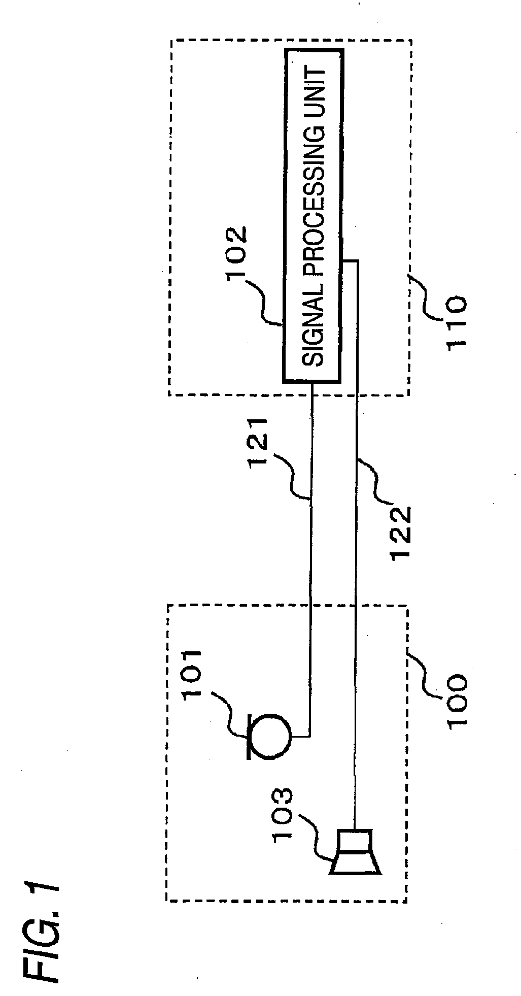
[0051]A drawing showing an example configuration of a hearing aid of a first embodiment of the present invention is provided in FIG. 1. The hearing aid of the present invention can be broadly divided into two constituent elements. One is an ear canal portion 100 that is disposed in at least either the inside of an ear canal or an entrance of the same when a behind-the-ear portion 110 to be described later is worn on an ear, and the other is the behind-the-ear portion 110 fitted to the ear so as to stay at an upper portion of the pinna and a position behind the pinna. The entrance of the ear canal refers to a portion that lies in an extension of the ear canal and closer to an eardrum than to a plane defined by the helix, the tragus, and the earlobe.

[0052]The ear canal portion 100 is configured to include a microphone 101 and a receiver 103. The behind-the-ear portion 110 includes signal processing unit 102. As electrical connections, the microphone 101 and the signal processing unit ...

second embodiment

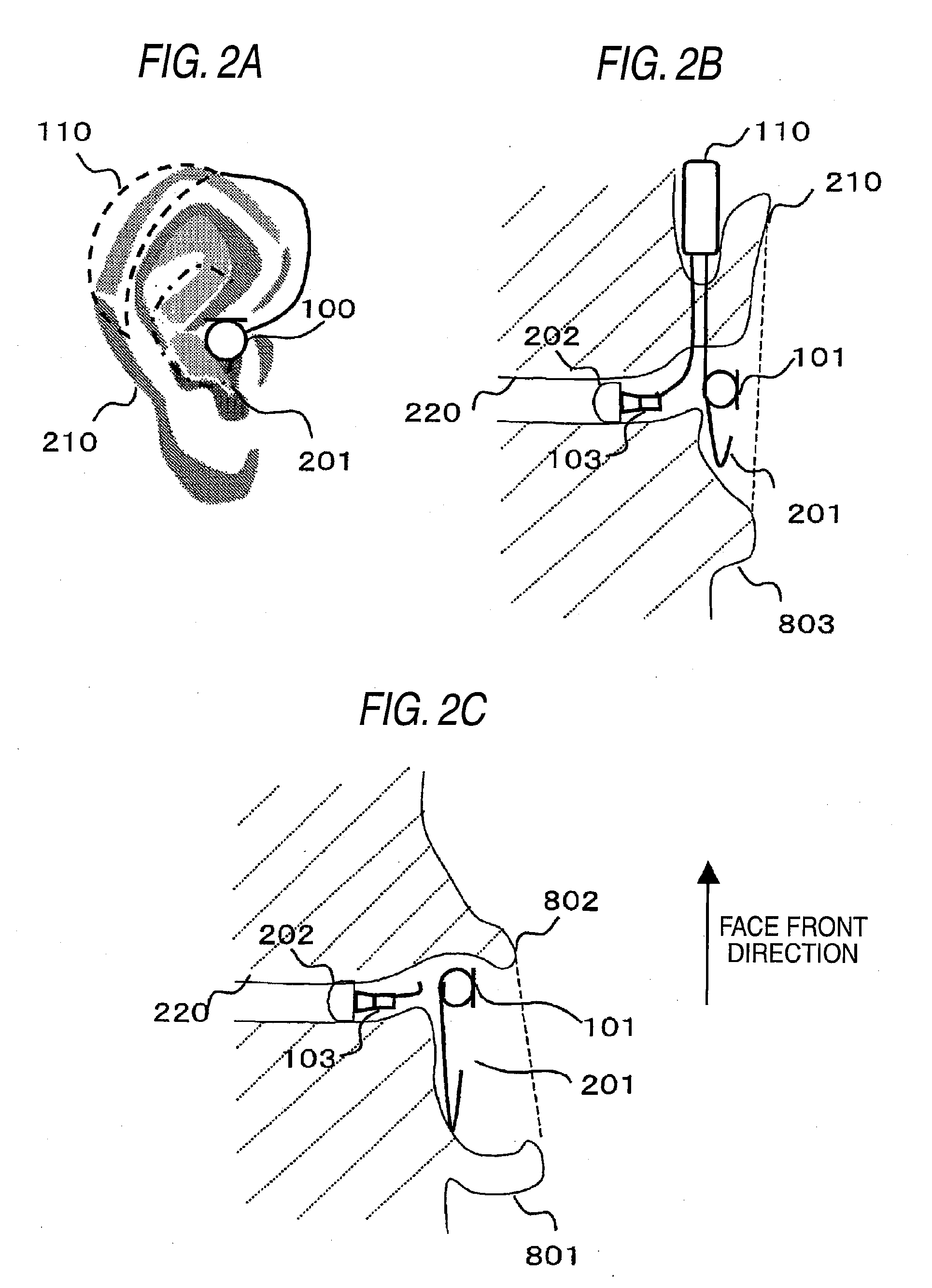
[0071]FIGS. 3 and 4 are schematic diagrams showing an example hearing aid of a second embodiment of the present invention and front views of the hearing aid with respect to the pinna to which the hearing aid is worn. In FIGS. 3 and 4, explanations for the elements that are the same as those shown in FIG. 2(a) are omitted; however, a new feature of the embodiment addresses to a plurality of microphones. Although two microphones are described in connection with FIGS. 3 and 4, the number of microphones is not limited to two.

[0072]In FIG. 3, when the behind-the-ear portion 110 is fitted to the ear, the two microphones are arranged in the entrance of the ear canal. In FIG. 3, what is disposed at a forward position with respect to the front of a face is a microphone 101F, and what is disposed at a rearward position with respect to the front of a face is a microphone 101R. What is important is that the microphone 101F and the microphone 101R are arranged front and back with respect to the ...


PUM


Abstract

There is provided a behind-the-ear hearing aid that makes it easy for a hearing aid wearer to estimate a position of a sound source with respect to a front-back direction and that enables an increase in aesthetic property when the hearing aid is worn. A behind-the-ear hearing aid of the present invention is used while fitted to an ear of a human body, and includes at least a microphone 101 which collects ambient sound, thereby generating an input signal and signal processing unit 102 that generates an output signal from the input signal. The hearing aid also has a behind-the-ear portion 110 that can be fitted to the ear and a receiver 103 that reproduces output sound from the output signal. When the behind-the-ear portion 110 is fitted to the ear, the microphone 101 is arranged in an entrance of an ear canal that lies in the extension of an ear canal 220 and that is disposed closer to an eardrum than to a plane that is defined by a helix 901, a tragus 902, and an earlobe 903.

Description

TECHNICAL FIELD[0001]The present invention relates to a behind-the-ear hearing aid whose microphone is set in an entrance of an ear canal.BACKGROUND ART[0002]As related hearing aids, the one is the behind-the-ear(BTE) hearing aids and the other is the in-the-ear(ITE) hearing aid. The ITE hearing aid includes a completely-in-the-canal hearing aid, a concha-type hearing aid and a canal-type hearing aid. Recently hearing aid users tend to prefer a BTE hearing aid to an ITE type, because the BTE hearing aid is compact and unobtrusive when the user put it on a behind a pinna.[0003]Some example, related-art behind-the-ear hearing aids have two constituent elements. The two constituent elements are a behind-the-ear (Behind The Ear: BTE) section and a completely-in-the-canal (Completely In the Canal: CIC) section. The BTE is equipped with a microphone, a battery, and signal processing unit; and a receiver is provided in an ear canal. Hitherto, a sound has been transmitted from a hearing aid...

Claims


Application Information

Patent Timeline
Patent Type & Authority Applications(United States)
IPC IPC(8): H04R25/00H04R25/02
CPCH04R25/407H04R25/453H04R2430/20H04R25/652H04R25/656H04R25/60H04R2225/57H04R1/40H04R3/00H04R3/02H04R25/00H04R25/02H04R1/1008
Inventor IWANO, KENJIKONDO, HIROSHI
Owner PANASONIC CORP
Why Eureka
Try Eureka