Injection Molding Valve Gated Hot Runner Nozzle

Active Publication Date: 2010-04-15
MOLD MASTERS 2007
View PDF28 Cites 14 Cited by
  • Summary
  • Abstract
  • Description
  • Claims
  • Application Information

AI Technical Summary

Problems solved by technology

In injection molding and in particular hot runner molds for injection molding managing the thermal transition at the mold gate between the hot runner side and the cold cavity side of the mold is a challenge.
Such heat trans

Method used


Image

  • Injection Molding Valve Gated Hot Runner Nozzle
  • Injection Molding Valve Gated Hot Runner Nozzle
  • Injection Molding Valve Gated Hot Runner Nozzle

Examples


Embodiment Construction

[0018]Specific embodiments of the present invention are now described with reference to the figures, wherein like reference numbers indicate identical or functionally similar elements. The following detailed description is merely exemplary in nature and is not intended to limit the invention or the application and uses of the invention. Furthermore, there is no intention to be bound by any expressed or implied theory presented in the preceding technical field, background, brief summary or the following detailed description.

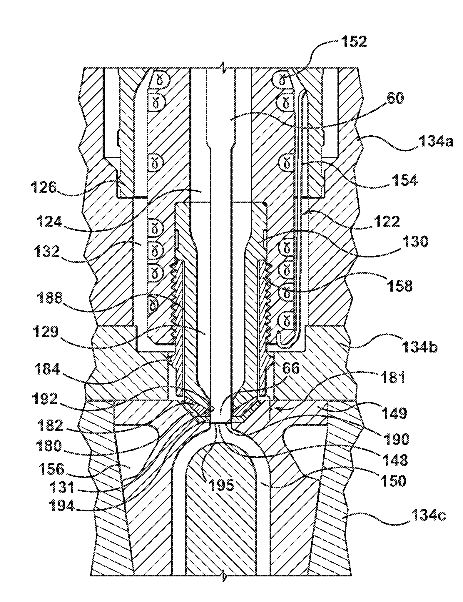
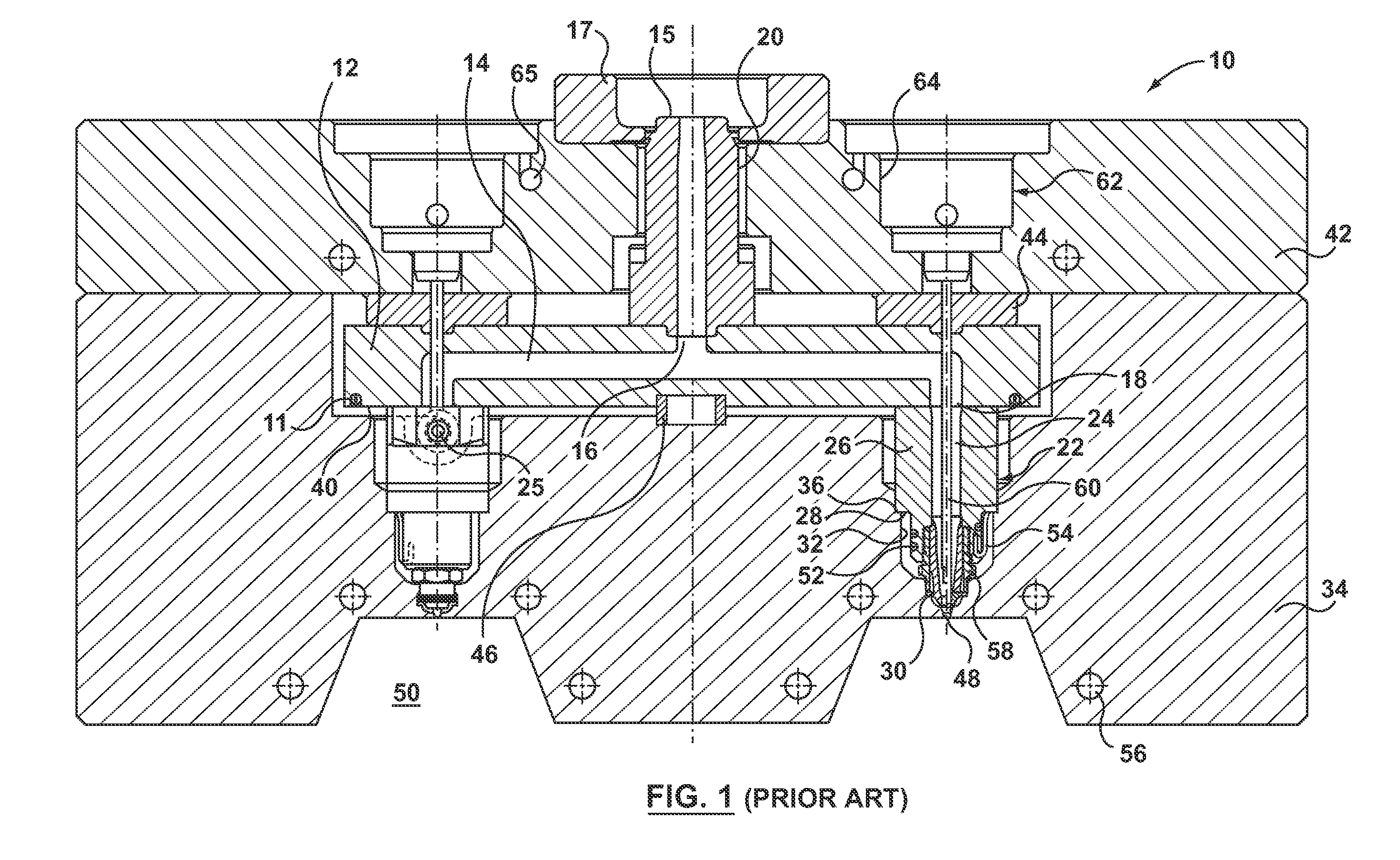
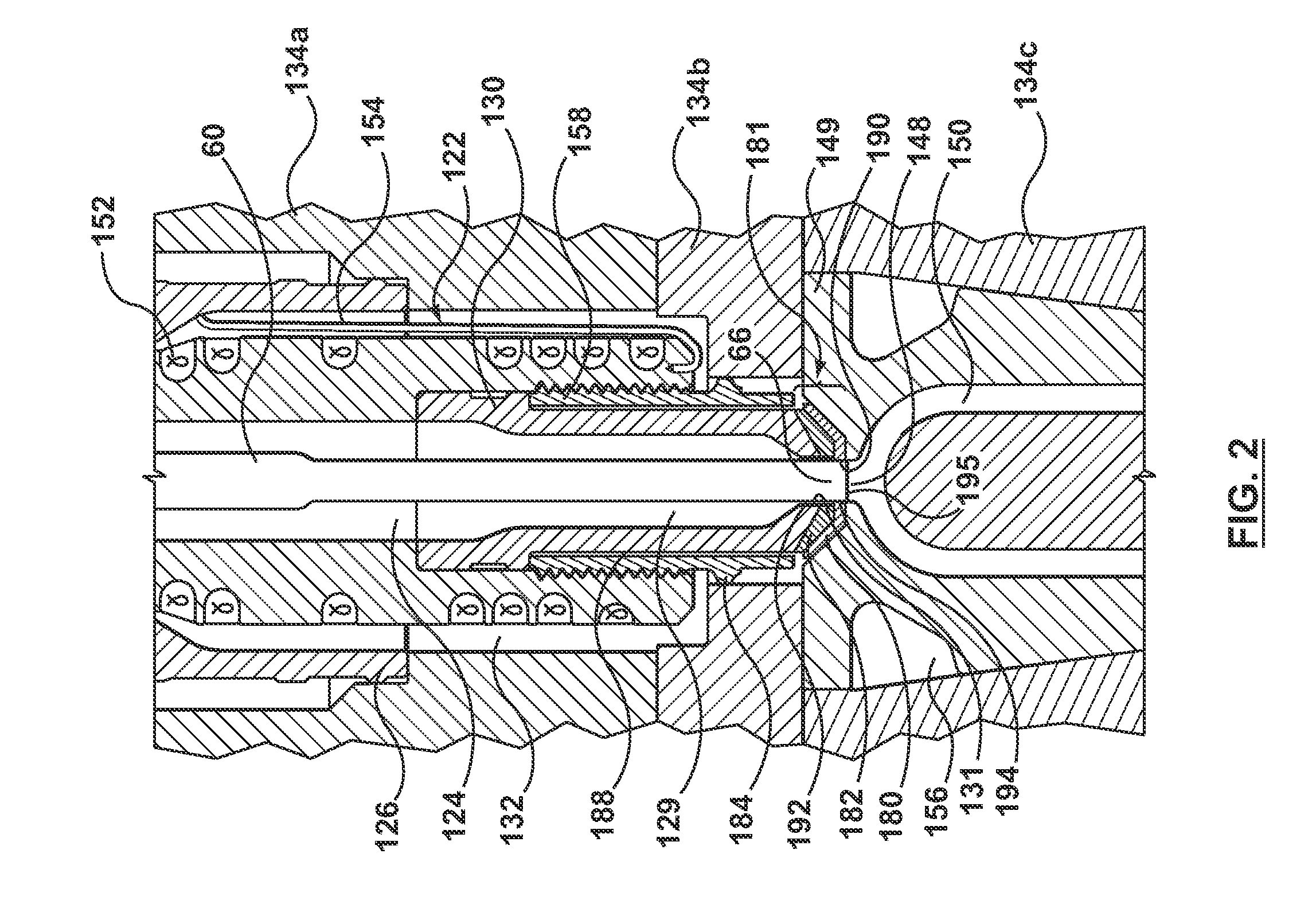
[0019]Embodiments hereof relate to, among other things, nozzles and components which can be used in injection molding apparatus such as the injection molding apparatus 10 shown in FIG. 1. Injection molding apparatus 10 includes a manifold 12 having a manifold melt channel 14 and a manifold heater 11. Manifold melt channel 14 extends from a manifold inlet portion 16 to manifold outlets 18. Manifold heater 11 can be of any design such as the insulated resistance wir...


PUM

PropertyMeasurementUnit
Temperatureaaaaaaaaaa
Shapeaaaaaaaaaa
Thermal conductivityaaaaaaaaaa

Abstract

A valve gated hot runner nozzle with at least two transition members made of different materials located between a nozzle tip and a mold gate component to provide a thermal transition region. A first transition member in contact with the nozzle tip is less thermally conductive than a second transition member in contact with the mold gate component. The valve pin when in the closed position makes sealing contact with at least the second transition member such that cooling from the mold gate component is transferred to the valve pin to cool the melt in the mold gate area.

Description

CROSS REFERENCE TO RELATED APPLICATION[0001]This application claims the benefit under 35 U.S.C. §119(e) of U.S. Appl. No. 61 / 104,427 filed Oct. 10, 2008, which is incorporated by reference herein in its entirety.FIELD OF THE INVENTION[0002]The present invention relates to injection molding and more particularly to a valve gated nozzle for a hot runner system.BACKGROUND OF THE INVENTION[0003]In injection molding and in particular hot runner molds for injection molding managing the thermal transition at the mold gate between the hot runner side and the cold cavity side of the mold is a challenge.[0004]In valve gated hot runner nozzles when the valve pin is seated in the mold gate in a closed position, the valve pin conducts heat from the molten material in the nozzle melt channel to the area of the mold gate. Such heat transfer makes it difficult to cool the mold gate area. Further, if the molded part is ejected before adequate cooling is achieved, the mold gate vestige on the molded ...

Claims


Application Information

Patent Timeline
IPC IPC(8): B29C45/74
CPCB29C45/0025B29C45/2711B29C2045/2787B29C45/2806B29C2045/2785B29C45/278
Inventor KLOBUCAR, PETERBABIN, DENISCATOEN, BRUCEGAMMON, SCOTT
Owner MOLD MASTERS 2007
Why Eureka
Try Eureka