Cable guard and guide for archery bows

a cable guard and archery bow technology, applied in the field of archery bows, can solve the problems of premature wear or abrasion of the cables, affecting the performance of the cable guard, so as to reduce the abrasion of the cable, reduce the friction, and efficiently guide one or more cables.

Inactive Publication Date: 2010-04-29
GRACE ENG
View PDF12 Cites 16 Cited by
  • Summary
  • Abstract
  • Description
  • Claims
  • Application Information

AI Technical Summary

Benefits of technology

[0010]In another embodiment, the cable guard bore can include a rounded or radiused opening or inner surface to minimize abrasion to the cable as the cable moves when the bow is drawn or shot.
[0011]In yet another embodiment, the cable guide can include a low friction element constructed from materials, such as a ceramics, composites or polymers. The low friction element can be include a rounded or radiused surface, such as an edge that engages the cable. Optionally, the low friction element can be included in a stationary cable guide, having no moving components, to engage and hold the cable away from the bowstring, while minimizing abrasion and / or friction on the cable and while remaining in substantially the same position relative to a riser of the bow.
[0013]In a further embodiment, the cable guide can include a moveable component, such as a cable guide that slides or rotates relative to the cable guard, or a cable guide including a rotatable pulley mounted to the cable guard. The low friction element can be positioned between the cable and the moveable component to reduce abrasion to the cable.
[0014]The archery bow provided herein provides cable guards and optional cable guides that efficiently guide one or more cables of the bow. Where included, the low friction element can reduce wear on the cables and therefore increase cable life, as well as improve cable movement and performance.

Problems solved by technology

Although this construction provides effective cable clearance, over time, the cable guide can wear, leading to abrasion or other damage to the cables.
Moreover, the sliding movement of the cable guide on the cable guard can also cause wear to both structures, and can undesirably complicate the assembly.
Although this design provides effective cable guidance, it too includes moving parts that must be monitored for wear and surfaces that can cause premature wear or abrasion on the cables.

Method used


Image

  • Cable guard and guide for archery bows
  • Cable guard and guide for archery bows
  • Cable guard and guide for archery bows

Examples


first alternative embodiment

III. First Alternative Embodiment

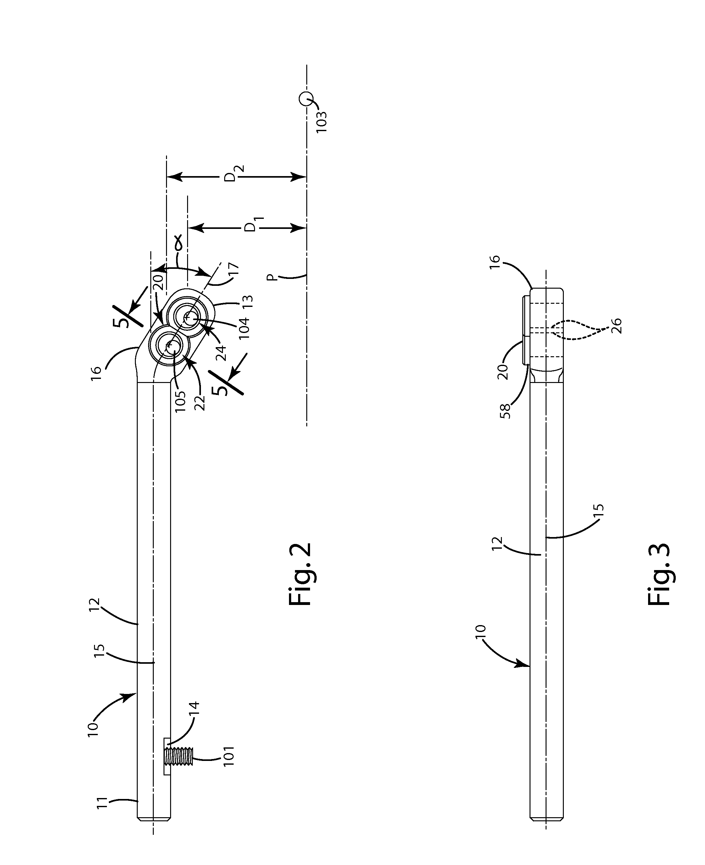
[0052]With reference to FIGS. 6 and 7, a first alternative embodiment of an archery bow including a cable guard and cable guide will now be described. In general, this first alternative embodiment is similar to the embodiment described above with a few exceptions. For example, the cable end 117 of the cable guard 110 is angled at a region 113 closer to the riser end 111 than that of the embodiment described above. The guide portion 116 can be angled relative to the remainder of the bar 112 at an angle α, optionally between about 0 and about 90 degrees, further optionally about 5 and about 35 degrees, and even further optionally about 11 degrees. At these angles, the cable guard 110 can achieve a suitable location of the cables in relation to the bow string 103 and the plane in which the bow string 103 moves. This angle can also provide suitable clearance for the vanes of an arrow shot from the bowstring 103.

[0053]As shown in FIG. 7, this embodiment c...

second alternative embodiment

IV. Second Alternative Embodiment

[0054]Referring to FIGS. 8 and 9, a second alternative embodiment of an archery bow including a cable guard and cable guide will now be described. In general, the second alternative embodiment is similar to the embodiment described above with a few exceptions. For example, instead of defining separate cable guard bores, the cable guard 210 includes a generally oblong or elongated cable guard bore 226 in which a single piece cable guide 220 is inserted. As shown in FIG. 9, that cable guide 220 can be in the form of an oblong cable guide insert 250 which defines cable guide bores 252, which can be configured similar to any of the internal bores of the embodiments described above.

[0055]The cable guide insert 250 can generally be constructed from a single integral piece of low friction material, such as glazed ceramic, or any of the other low friction materials mentioned above. The respective ingresses and egresses of the bores 254, can have radii and / or...

third alternative embodiment

V. Third Alternative Embodiment

[0057]A third alternative embodiment of the archery bow 100 including the cable guard 310 and cable guide 320 is shown in FIGS. 10 and 11. In general, this embodiment is similar to the above embodiments with a few exceptions. For example, this embodiment includes a mounting bracket 60. The mounting bracket 60 includes a boss 62 adapted to be inserted into a bore of the bow riser 302. Optionally, the boss can be held in the bore of the riser 302 by threading or a set screw as described above, or other mechanisms. The mounting bracket also includes an offset portion 65 that extends away from the boss. This offset portion can define a bore 64. The axis of this bore 64 can be offset from the axis of the boss 62. The bore 64 can be sized to provide a sliding fit for the riser end of the cable guard 310.

[0058]The mounting bracket can enable the cable guard 310 to be moved within the bore 64 in the directions shown by the arrow Z, toward and away from the ris...


PUM


Abstract

An archery bow includes a cable guard and an optional cable guide that holds a cable of the bow away from a plane in which a bowstring of the bow moves. The cable guard can define a bore, through which the cable is positioned, extending generally parallel to the bowstring when the bowstring is in an undrawn state. The cable guard bore can include a rounded opening to minimize abrasion to the cable. The cable guide can include a ceramic element having a rounded surface to minimize abrasion to the cable. The ceramic element can be included in an immovable or stationary cable guide, as well as an alternative cable guide including moving components, to engage and hold the cable away from the bowstring, while minimizing abrasion and / or friction on the cable.

Description

[0001]This application is a divisional of U.S. application Ser. No. 12 / 564,508, filed Sep. 22, 2009, and claims the benefit of U.S. Provisional Application 61 / 102,472, filed Oct. 3, 2008, both of which are hereby incorporated by reference.BACKGROUND OF THE INVENTION[0002]The present invention relates to archery bows, and more particularly to a cable guard and cable guide for archery bows.[0003]Conventional compound archery bows include a bowstring and a set of cables, usually an up cable and a down cable, to transfer energy from the limbs and cams or pulleys (which are both referred to generally as “cams” herein) of the bow to the bowstring, and thus an arrow shot from the bow. The cables and bowstring are strung from a cam on one limb to a cam on another limb. Typically, the bowstring is positioned very close to the cables due to the configuration of the cams. To avoid interference between the vanes of an arrow shot from the bowstring and the cables, most compound bows include cabl...

Claims


Application Information

Patent Timeline
Patent Type & Authority Applications(United States)
IPC IPC(8): F41B5/10F41B5/14
CPCF41B5/14F41B5/10
Inventor GRACE, NATHANIEL E.GRACE, JR., LOUISSTOKES, KYLE B.
Owner GRACE ENG
Why Eureka
Try Eureka