
Head slider and method of making the same and grinding apparatus for head slider

Inactive Publication Date: 2008-05-01
TOSHIBA STORAGE DEVICE CORP
View PDF7 Cites 16 Cited by
  • Summary
  • Abstract
  • Description
  • Claims
  • Application Information

AI Technical Summary

Benefits of technology

[0007]It is accordingly an object of the present invention to provide a drive capable of reliably detecting contact between a protection film and a storage medium when a head element protrudes. It is also an object of the present invention to provide a method of making such a drive. Moreover, it is also an object of the present invention to provide a head slider, a method of making the head slider, and a grinding apparatus for the head slider, all significantly contributing to realization of the drive.
[0009]The ground surface has a larger area to contact with the storage medium during a so-called zero calibration, for example. An urging force per unit area is thus reduced. This results in minimization of abrasion of the protrusion. Moreover, the ground surface instantaneously sticks to the surface of the storage medium. This results in generation of a slight vibration or sway of the head slider. Contact can reliably be detected between the head slider and the storage medium in response to the vibration. In the case where the tip end of the protrusion on the second protecting film is pointed, the protrusion is prevented from sticking to the surface of the storage medium. This results in prevention of generation of a slight vibration or sway of the head slider. Even if the protrusion contacts with the storage medium, the detection of the contact is thus sometimes missed.
[0010]A specific method may be provided to make the aforementioned drive. The method may comprise: causing a head element to protrude toward a storage medium with the assistance of a heater, the head element embedded in a non-magnetic insulating film overlaid on the outflow end surface of the slider body of a head slider, the heater embedded in the non-magnetic insulating film in connection with the head element; detecting contact between the storage medium and a protection film covering over the head element; and increasing the protrusion amount of the head element when the contact has been detected.
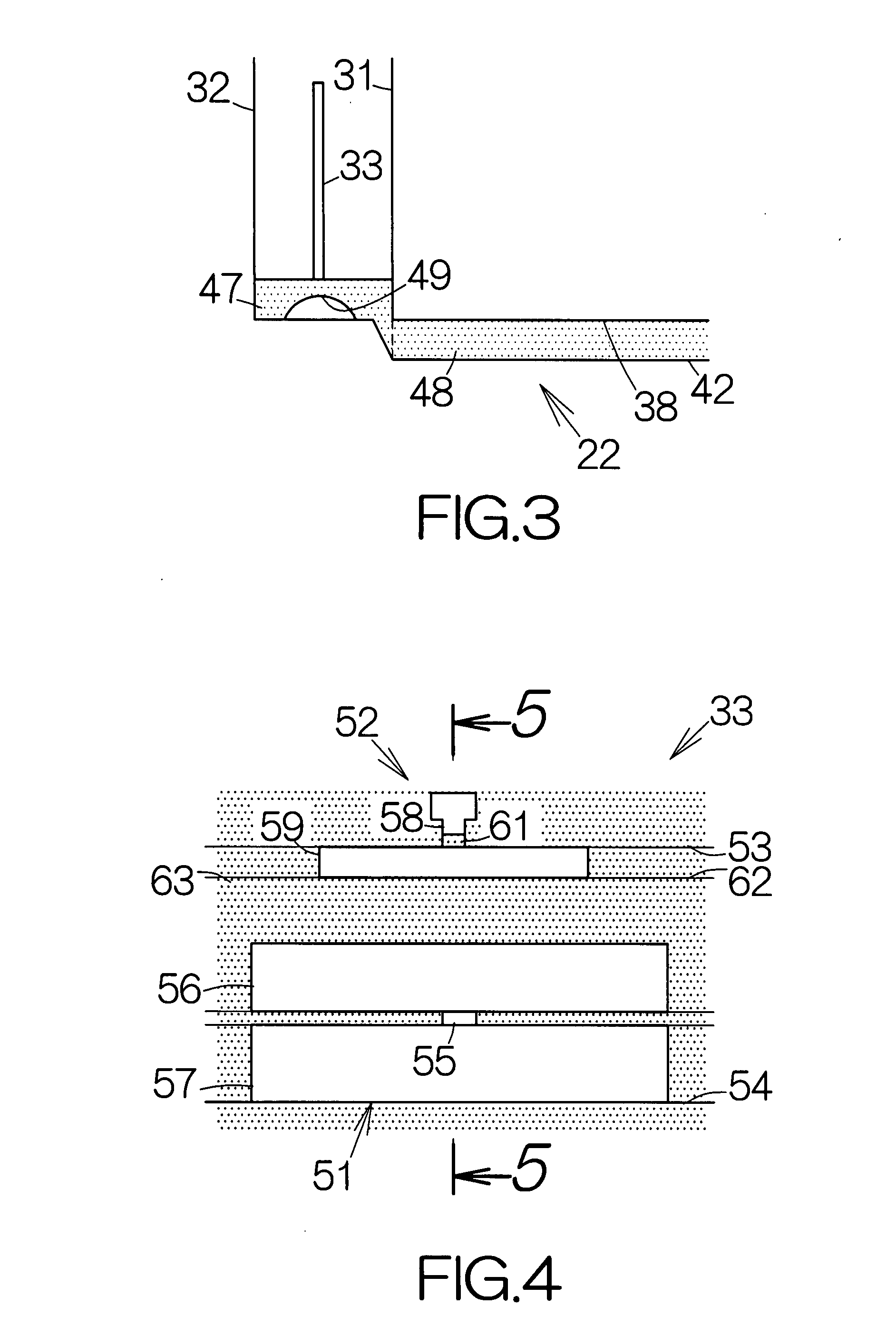
[0011]The method allows formation of the protection film on the top surface of a rail and the surface of the non-magnetic insulating film prior to formation of a ground surface. The thickness of the protection film is set larger than the minimum thickness required for protection of the head element. The ground surface is formed based on the protection film having such a larger thickness. When the protection film forms a protrusion in response to the heat generated by the heater, the tip end of the protrusion thus establishes a relatively smooth curved surface. This results in a reliable realization of “attachment” or “adhesion” of the protrusion to the storage medium when the protrusion contacts with the storage medium. The contact can thus reliably be detected between the protection film and the storage medium. In the case where the thickness of the protection film is relatively small, the tip end of the protrusion tends to get pointed. The pointed tip end of the protrusion prevents detection of the contact between the protection film and the recording medium. The ground surface is thus excessively ground. The total duration of contact may be set in a range from 0.004 seconds to 3,000 seconds between the storage medium and the protection film, for example. The surface roughness Ra of the storage medium may be set in a range from 0.3 nm to 3.0 nm, for example. The head element may read out magnetic bit data held on the storage medium when increasing the protrusion amount. The output from the head element has a certain correlation with the distance between the head element and the storage medium. The distance between the head element and the storage medium can thus be estimated based on the output from the head element during the grinding. The ground amount can in this manner be grasped with a high accuracy.
[0012]The method may further comprise: placing the storage medium in the enclosure of the drive; and placing the head slider in the enclosure of the drive prior to protrusion of the head element. The ground surface can thus be formed after the drive has been assembled. A read signal output from the head element may be utilized to detect the contact. Utilization of the read signal enables the detection of the contact between the protection film and the storage medium without any additional signal wire. Since the ground surface enables the reliable “attachment” or “adhesion” of the protrusion when the protrusion contacts with the storage medium in the same manner as described above, a sign of the contact reliably appears in the read signal.

Problems solved by technology

This results in minimization of abrasion of the protrusion.
This results in generation of a slight vibration or sway of the head slider.

Method used


Image

  • Head slider and method of making the same and grinding apparatus for head slider
  • Head slider and method of making the same and grinding apparatus for head slider
  • Head slider and method of making the same and grinding apparatus for head slider

Examples


Embodiment Construction

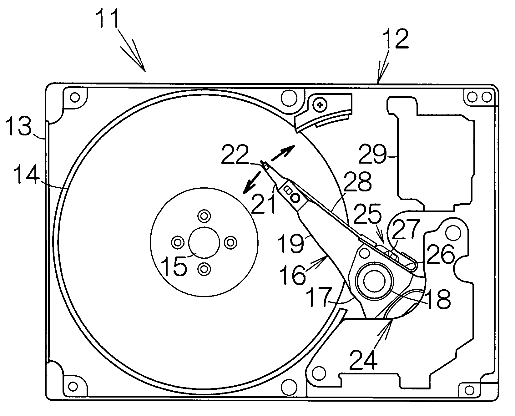
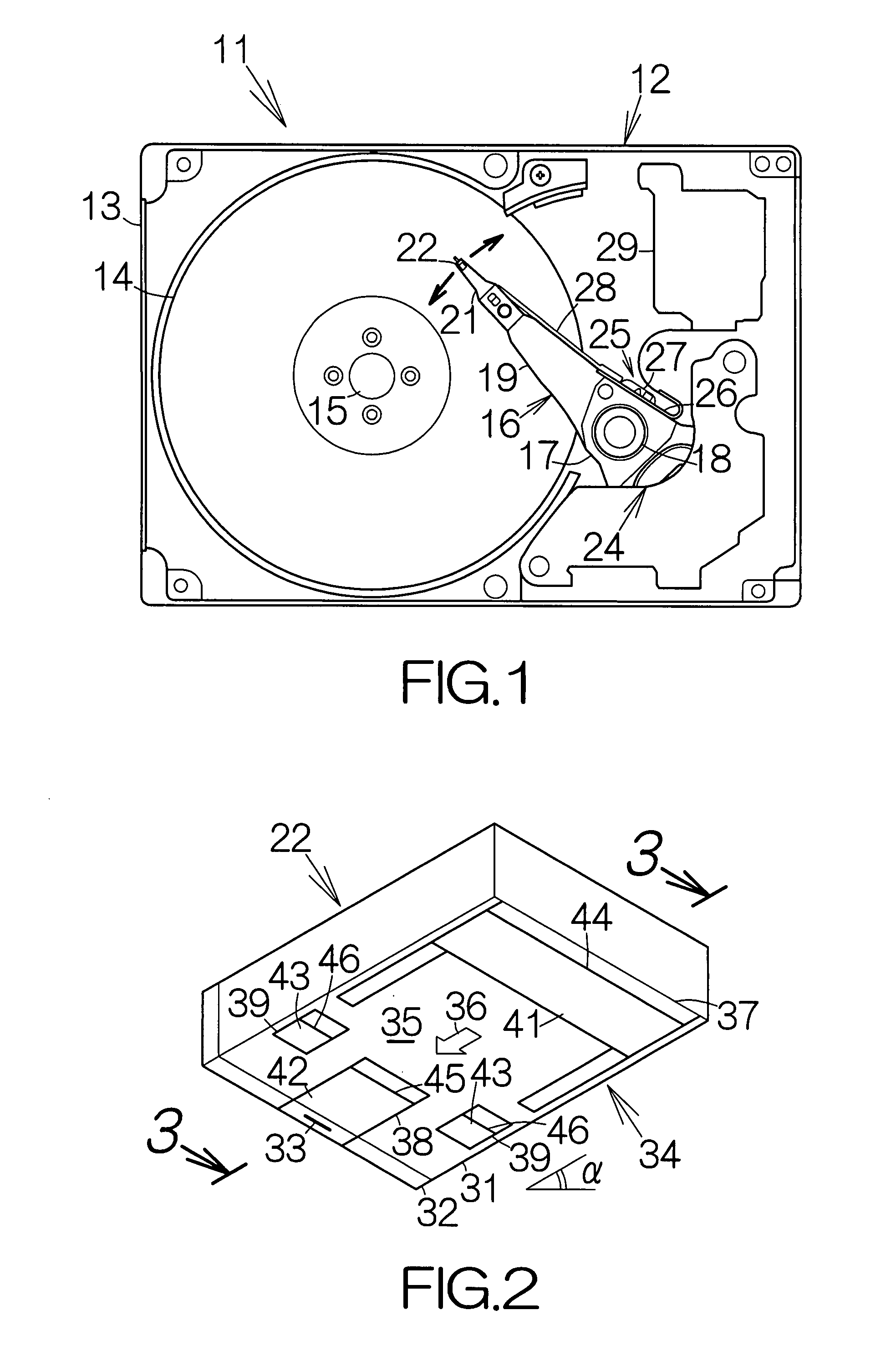
[0029]FIG. 1 schematically illustrates the inner structure of a hard disk drive, HDD, 11 as an example of a drive or a storage device according to the present invention. The hard disk drive 11 includes an enclosure 12. The enclosure 12 includes a box-shaped base 13 and an enclosure cover, not shown. The base 13 defines an inner space in the form of a flat parallelepiped, for example. The base 13 may be made of a metallic material such as aluminum, for example. Molding process may be employed to form the base 13. The enclosure cover is coupled to the base 13 to close the opening of the base 13. An airtight inner space is defined between the base 13 and the enclosure cover. Pressing process may be employed to form the enclosure cover out of a plate material, for example.

[0030]At least one magnetic recording disk 14 as a storage medium is enclosed in the inner space of the base 13. The magnetic recording disk or disks 14 are mounted on the driving shaft of a spindle motor 15. The spind...


PUM


Abstract

A head slider includes a non-magnetic insulating film overlaid on the outflow end surface of a slider body. A second protection film is overlaid on the surface of the non-magnetic insulating film. A heater is embedded in the non-magnetic insulating film to induce a protrusion of the non-magnetic insulating film. A flat ground surface is formed on the second protection film at the tip end of the protrusion. The ground surface has a larger area to contact with a storage medium during a so-called zero calibration. An urging force per unit area is thus reduced. This results in minimization of abrasion of the protrusion. The ground surface instantaneously sticks to the surface of the storage medium. This results in generation of a slight vibration of the head slider. Contact can reliably be detected between the head slider and the storage medium in response to the vibration.

Description

BACKGROUND OF THE INVENTION[0001]1. Field of the Invention[0002]The present invention relates to a head slider incorporated in a drive such as a hard disk drive, HDD. In particular, the present invention relates to a head slider including a heater embedded in a non-magnetic film in connection with a head element.[0003]2. Description of the Prior Art[0004]A non-magnetic film made of Al2O3 (alumina) is overlaid on a slider body made of Al2O3—TiC in a head slider, for example. A head element and a heater are embedded in the non-magnetic film. A protection film made of diamond-like-carbon (DLC) is formed on the surface of the non-magnetic film, for example. The protection film covers over the read gap and the write gap of the head element.[0005]Heat of the heater is applied to a thin film coil pattern in the head element. The thermal expansion of the thin film coil pattern enables the read gap and the write gap of the head element to approach a magnetic recording disk. The flying height...

Claims


Application Information

Patent Timeline
IPC IPC(8): G11B5/60
CPCG11B5/3133G11B5/6005G11B5/3169G11B5/3166G11B5/607G11B21/21G11B5/60
Inventor OZEKI, MASAHIRO
Owner TOSHIBA STORAGE DEVICE CORP
Learn More