190w power limiter circuit for lighting equipment

Inactive Publication Date: 2010-04-29
WU HSI CHOU
View PDF3 Cites 0 Cited by
  • Summary
  • Abstract
  • Description
  • Claims
  • Application Information

AI Technical Summary

Benefits of technology

[0005]The object of this invention is to offer a 190 W power limiter circuit for lighting equipment. That is, power consumption of the lamps can be always

Problems solved by technology

However, when extra lamps are installed by a user, a regulation restricting a load less than 190 W ma

Method used


Image

  • 190w power limiter circuit for lighting equipment
  • 190w power limiter circuit for lighting equipment
  • 190w power limiter circuit for lighting equipment

Examples


Embodiment Construction

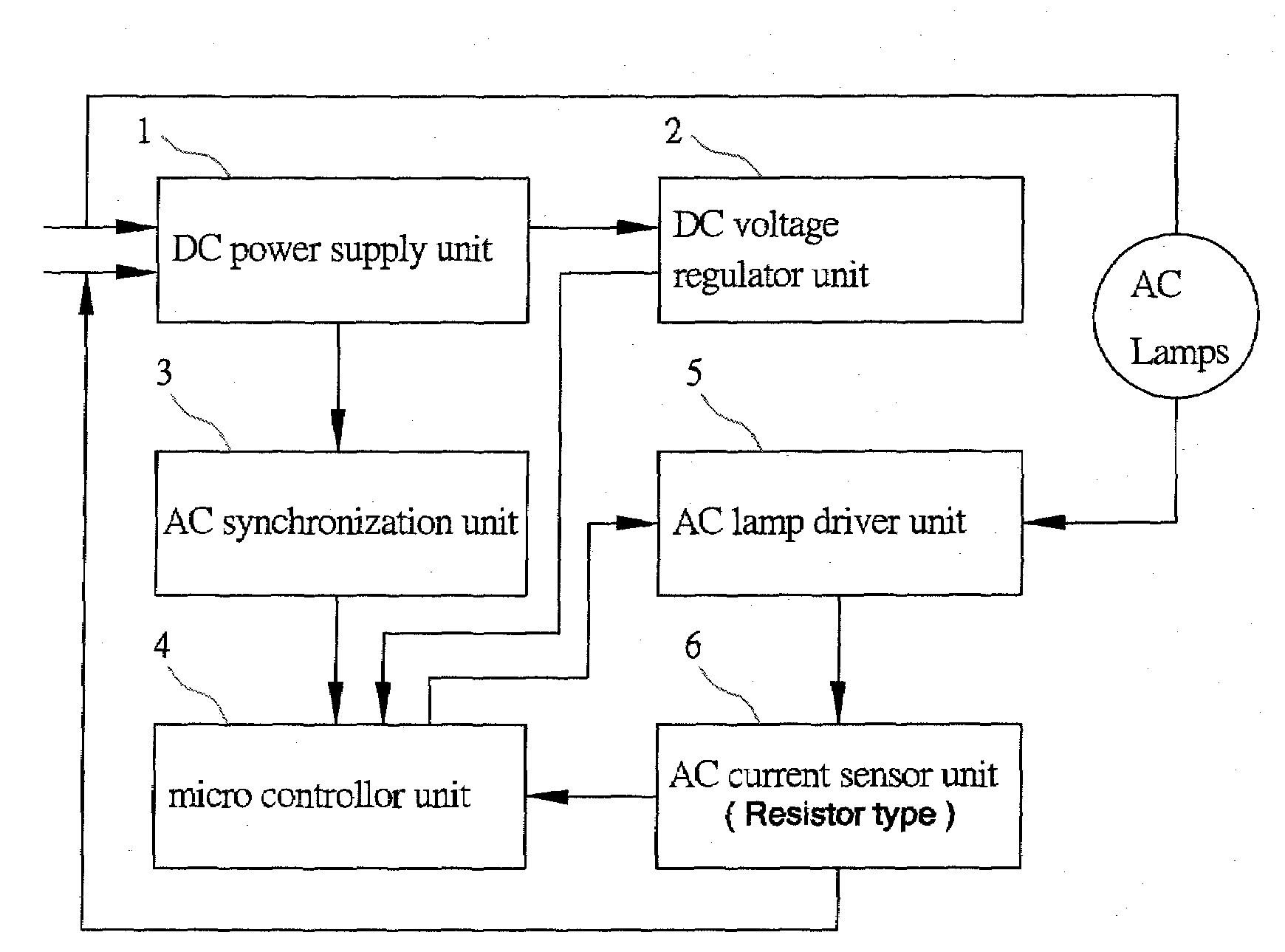
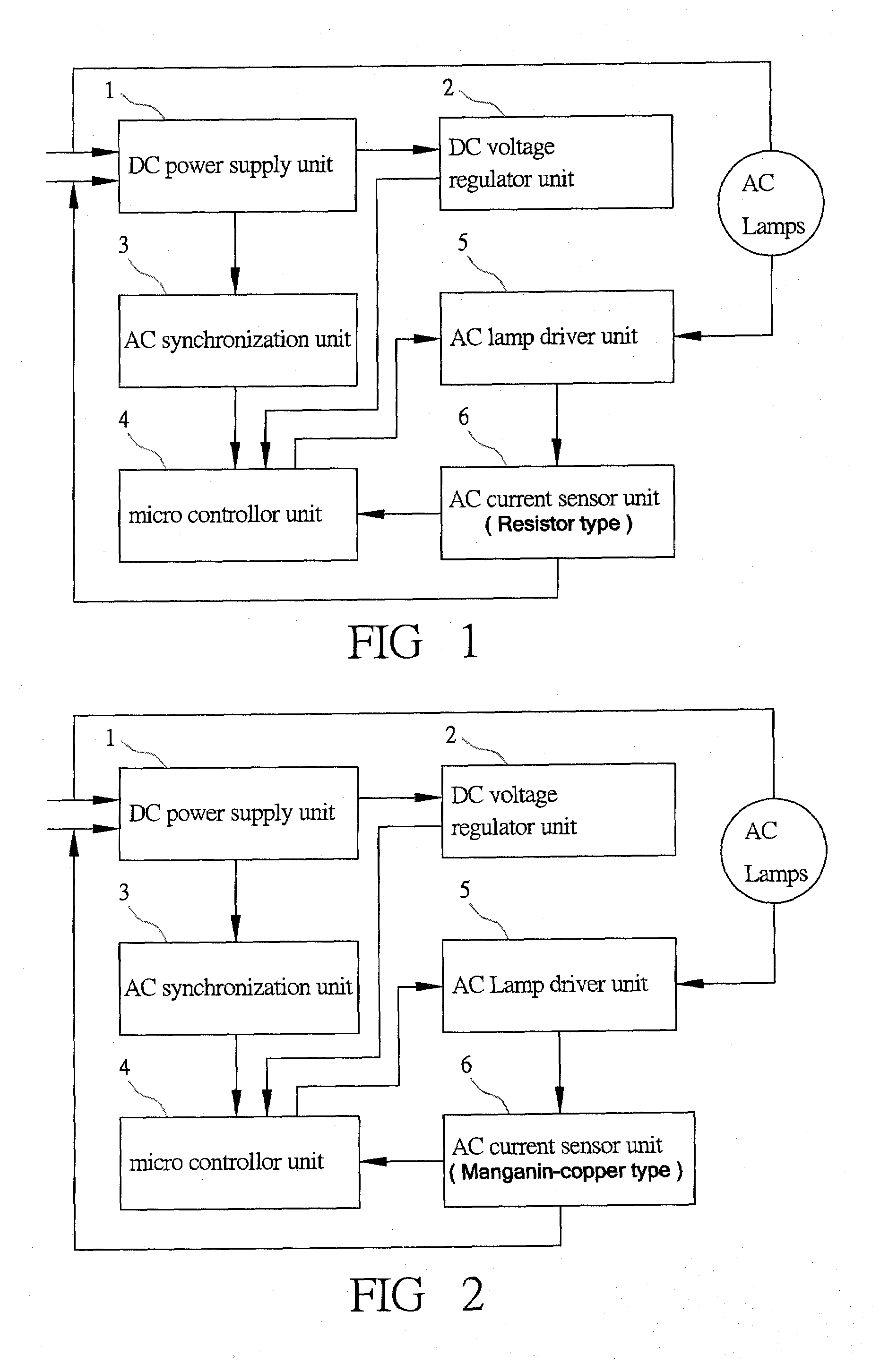
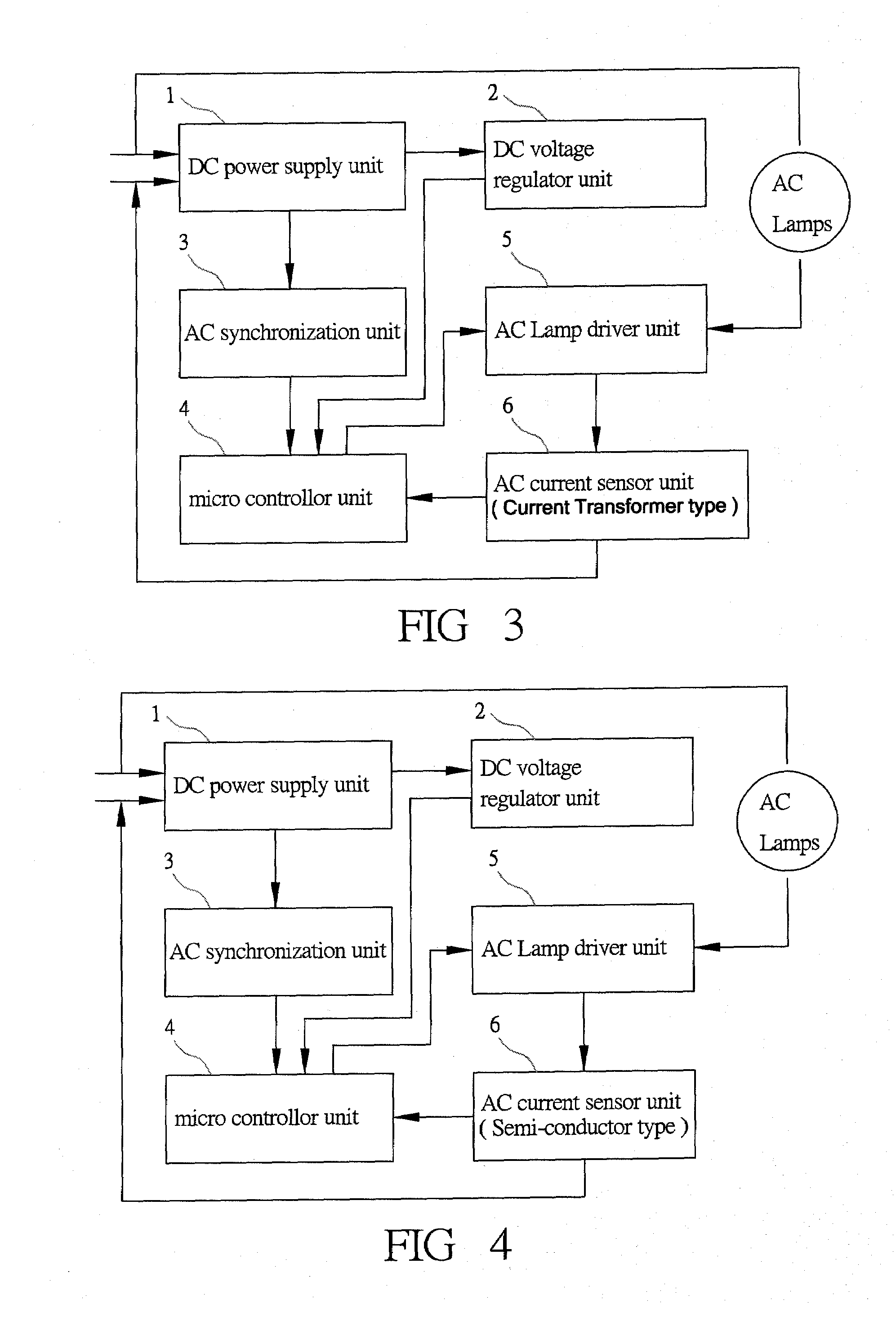
[0017]As shown in FIG. 1, a first preferred embodiment of a 190 W power limiter circuit for lighting equipment in the present invention includes a DC power supply unit 1, an DC voltage regulator unit 2, an AC synchronization unit 3, a micro controller unit 4, an AC lamp driver unit 5 and an AC current sensor unit 6.

[0018]The DC power supply unit 1 is directly connected with an AC power source, employed to transform the high voltage of the AC power source into a low DC output voltage so as to supply power for successive units.

[0019]The DC voltage regulator unit 2 is connected to the DC power supply unit 1, used to regulate the voltage of the current outputted from the DC power supply unit 1 to the micro controller unit 4.

[0020]The AC synchronization unit 3 is connected with the DC power supply unit 1, used to receive the AC synchronization signal and the AC voltage variation coming from the DC power supply unit 1, with the signals consecutively sent to the micro controller unit 4.

[00...


PUM


Abstract

A 190 W power limiter circuit for lighting equipment includes a DC power supply unit employed to transform an AC power source into a low DC output voltage, a DC voltage regulator used to regulate the DC power supply unit for a micro controller unit, an AC synchronization unit utilized to receive a synchronization signal of an AC line frequency and an AC voltage variation that are sent to the micro controller unit to achieve a synchronous triggering with the AC line frequency for driving an AC lamp driver unit, and an AC current sensor unit used to induct AC of a load circuit and having a resistor, manganese copper, a semi-conductor IC or a current transformer, which is connected to AC lamps in series, able to create voltage inducting signals fed back to the micro controller unit to adjust a triggering angle of the AC lamp driver unit for keeping power consumption less than 190W despite the load change of the lamps.

Description

BACKGROUND OF THE INVENTION[0001]1. Field of the Invention[0002]This invention relates to a 190 W power limiter circuit for lighting equipment, particularly to one installed with a DC current sensor unit provided with a resistor, manganese copper, a semi-conductor IC or a current transformer, which are connected to AC lamps in series, able to create voltage inducting signals corresponding to alternative current of a load circuit. The inducting signals are then fed back to the micro controller unit that is to consecutively analyze the AC synchronization signal and the AC voltage variation signal to output an adjusted signal for being synchronous with the AC line frequency to adjust a triggering angle of the AC lamp driver unit. Thus, power consumption of lamps can be kept less than 190 W no matter how the load of lamps is enlarged or how the AC voltage or the alternative current of the load is changed.[0003]2. Description of the Prior Art[0004]Commonly, conventional house lamps or th...

Claims


Application Information

Patent Timeline
IPC IPC(8): H05B41/36
CPCY02B20/146H05B39/044Y02B20/00
Inventor WU, HSI-CHOU
Owner WU HSI CHOU
Why Eureka
Try Eureka