
Docking charger for charging a hand held electronic device with or without a protective cover case fitted thereon

a charger and electronic device technology, applied in the direction of digital data processing details, instruments, transportation and packaging, etc., can solve the problems of chaotic desktop arrangement and inconvenience for users

Active Publication Date: 2010-04-29
UNKNOWN
View PDF18 Cites 48 Cited by
  • Summary
  • Abstract
  • Description
  • Claims
  • Application Information

AI Technical Summary

Benefits of technology

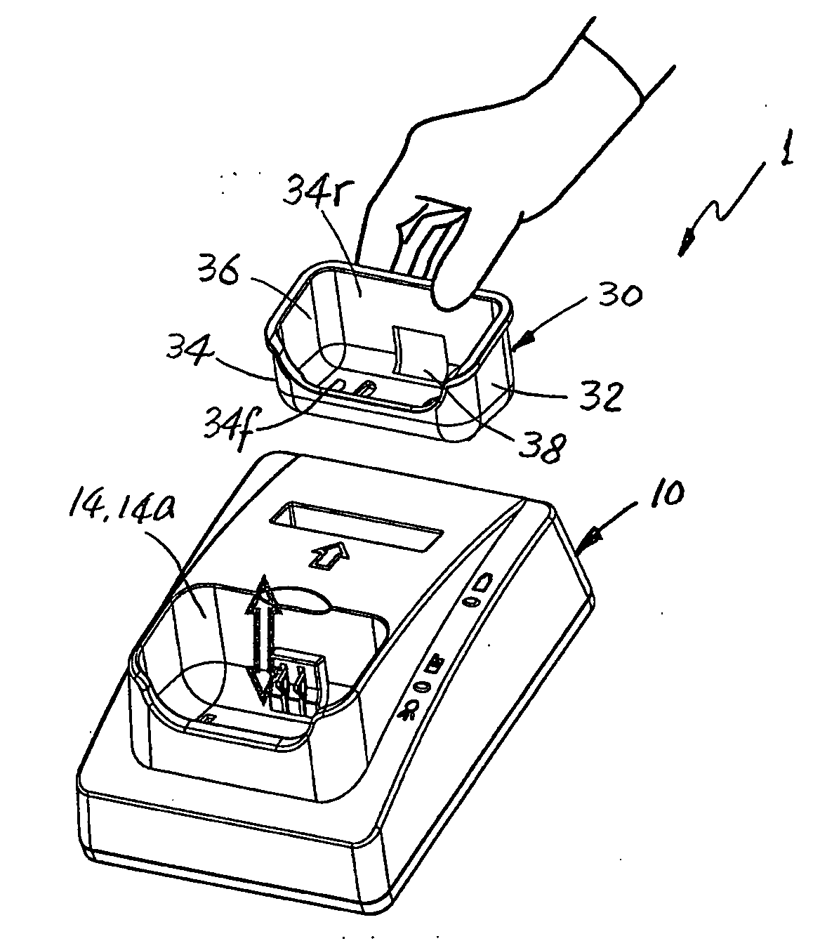
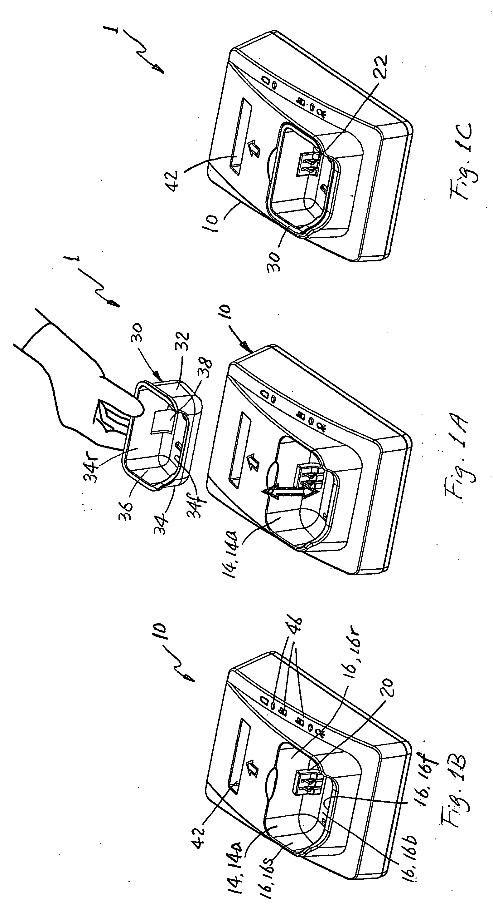
[0009]The embodiments disclosed herein relate generally to a docking charger for any of various hand held electronic devices. The docking charger has a docking base formed with a reception area. The reception area has a predetermined shape and size to support and hold the hand held electronic device in a charging position when the protective cover case is fitted on the electronic device. The docking charger also has a charger adapter formed to be removably fitted in the reception area of the docking base. The charger adapter has an interior chamber shaped and sized to directly support and hold the hand held electronic device in the charging position when the protective cover case is removed from the electronic device.

Problems solved by technology

When charging such a hand held electronic device, a user often has to remove the cover case before placing the hand held electronic device inside the docking charger for charging the battery.
Such additional steps of removing and refitting the cover case cause inconvenience to the user each time when the hand held electronic device is to be charged.
When different types or models of hand held electronic devices are to be charged, multiple desktop chargers are to be provided, which can create a chaotic desktop arrangement.

Method used


Image

  • Docking charger for charging a hand held electronic device with or without a protective cover case fitted thereon
  • Docking charger for charging a hand held electronic device with or without a protective cover case fitted thereon
  • Docking charger for charging a hand held electronic device with or without a protective cover case fitted thereon

Examples


first embodiment

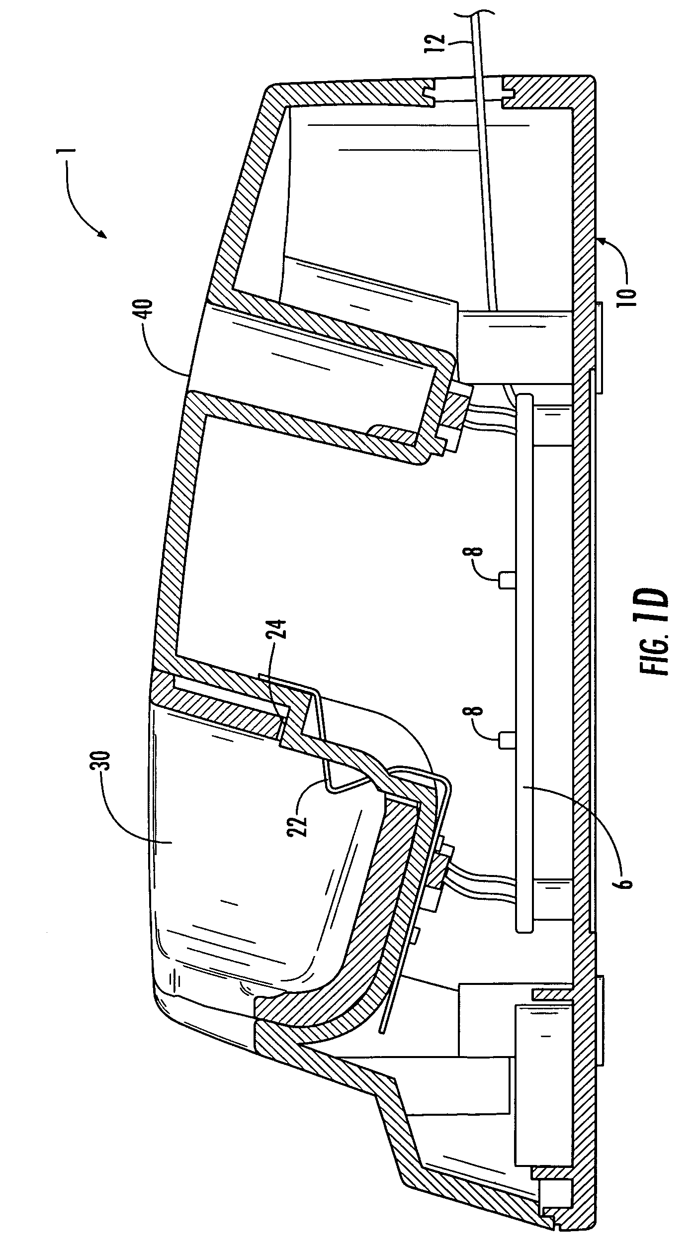
[0027]FIGS. 1A to 1D show a docking charger 1 for charging any of various hand held electronic devices 2 as described above. The docking charger 1 can include a docking base 10, which can be configured to be connected to any of various power sources, such as a standard AC outlet, automobile 12V supply, or a low voltage 5V supply. Various connectors, such as a power cord 12, can be used to connect the docking base 10 to a power source. For example, the power cord 12 can have a USB terminal for connecting to a USB port formed a power adapter device.

[0028]Additionally or alternatively, the docking base 10 can be configured to connect to a computer device, such as by a USB cable, for data transfer.

[0029]The docking base 10 has a reception area 14 formed to accommodate a hand held electronic device 2 during the battery charging operation as is described in details below. In one embodiment shown in FIGS. 1A and 1B, the reception area 14 is formed by surrounding walls 16 including a front ...

second embodiment

[0058]FIGS. 5A to 5D show the docking charger 1, in which the charging connector 20 is formed on the bottom of the reception area 14. The charging connector 20 can extend or otherwise be elevated from the bottom 16b of the receiving chamber 14a. Additionally or alternatively, the base portion 24 is formed to have a height measured from the bottom 16b of the reception area 14. The height of the base portion 24 is so provided to elevate the contact portions 22 so that they are spaced from the bottom of the reception area 14 for a predetermined distance. In one example, such distance is at least the same as the thickness of the cover case 4 of the hand held electronic device 2. The base portion 24 so formed can fill the gap between the charging connector 20 and the cover case 4 and thus assist in positioning the hand held electronic device 2 in place during the battery charging operation.

[0059]In an alternative embodiment shown in FIG. 5D, the charger adapter 30′ can be formed by a plu...

third embodiment

[0068]FIGS. 6A to 6C show the docking charger 1, in which the reception area 14 of the docking base 10 and / or the charger adapter 30 are formed with different configurations. For example, the reception area 14 is formed to support a side portion of a hand held electronic device 2, such as smart phone, fitted with a cover case 4. In one example, the reception area 14 can be defined by the front and rear walls 16f, 16r, without lateral side walls, such as the lateral side walls 16s shown in FIG. 1B. In another example not shown, the reception area 14 can be formed without a front wall, such as the front wall 16f shown in FIG. 1B.

[0069]The charger adapter 30 of the docking charger 1 can be similarly formed to be fitted inside the reception area 14. In the example shown in FIG. 6B, the charger adapter 30 can have open lateral sides. In examples not shown, the charger adapter 30 can be formed to have a C-shaped or L-shaped cross section or a plate shape. The charger adapter 30 as well as...


PUM


Abstract

The embodiments relate generally to a docking charger for charging a hand held electronic device. The docking charger has a docking base formed with a reception area. The reception area has a shape and size to support and hold the hand held electronic device in a charging position when the protective cover case is fitted on the hand held electronic device. The docking charger also has a charger adapter formed to be removably fitted in the reception area of the docking base. The charger adapter has an interior chamber shaped and sized to directly support and hold the hand held electronic device in the charging position when the protective cover case is removed from the hand held electronic device. The docking charger has two working positions. In the first working position where the charger adapter is removed from the reception area of the docking base, the reception area is exposed to receive the hand held electronic device fitted with its protective cover case. In the second working position, the charger adapter is fitted inside the reception area of the docking base to directly receive the hand held electronic device free of its protective cover case.

Description

CROSS-REFERENCE TO RELATED APPLICATION[0001]This patent application claims priority from U.S. Provisional Patent Application No. 61 / 109,423 filed Oct. 29, 2008.BACKGROUND OF THE INVENTION[0002]1. Field of the Invention[0003]The present invention relates generally to a docking charger for a hand held electronic device. More specifically, the invention relates to a docking charger configured to accommodate a hand held electronic device with and without its protective cover case fitted thereon. The invention also relates to a removable charger adapter for use in a base of a docking charger to allow a user to charge a hand held electronic device with and without its protective cover case fitted thereon.[0004]2. Description of the Related Art[0005]Various docking chargers have been used for charging hand held electronic devices. Typically, a hand held electronic device is directly received in a docking charger during the charging operation with the battery remaining in the hand held elec...

Claims


Application Information

Patent Timeline
IPC IPC(8): H02J7/00
CPCH02J7/0044G06F1/1626G06F2200/1633H02J7/0042H04M1/04G06F1/1632
Inventor SA
Owner UNKNOWN
Learn More