
Eyepiece lens system, finder optical system, and electronic viewfinder of imaging apparatus and imaging apparatus

a technology of optical system and optical lens, which is applied in the field of optical system of optical lens, finder optical system, electronic viewfinder of imaging apparatus and imaging apparatus, can solve the problems of not meeting the demand, not having the technology described in jp-a-, and not having the problem of high-definition observation

Inactive Publication Date: 2010-04-29
PANASONIC CORP
View PDF1 Cites 21 Cited by
  • Summary
  • Abstract
  • Description
  • Claims
  • Application Information

AI Technical Summary

Benefits of technology

"The present invention provides an electronic viewfinder with a high-definition observation capability. An eyepiece lens system is used to display the image from the electronic viewfinder. The eyepiece lens system comprises three lenses with specific refractive indices and positioned in a specific order. The system satisfies certain conditions to achieve high-definition viewing. The finder optical system, electronic viewfinder, and imaging apparatus comprising the eyepiece lens system are also provided. The technical effect of the invention is to provide an improved viewing experience for the user of the electronic viewfinder."

Problems solved by technology

Thus, none of the techniques described in JP-A-2002-48985 and JP-A-6-258582 meet such a demand.
Thus, RGB colors that are normally mixed in one dot are separated and even when green stays within one dot and thus appears not blurred, blue and red appear blurred, which causes a problem in terms of high-definition observation.
In addition, in the eyepiece lens system described in JP-A-6-258582, a magnification of only 4× is available and thus there is a problem in terms of large-scale observation with an ultra-compact LCD.

Method used


Image

  • Eyepiece lens system, finder optical system, and electronic viewfinder of imaging apparatus and imaging apparatus
  • Eyepiece lens system, finder optical system, and electronic viewfinder of imaging apparatus and imaging apparatus
  • Eyepiece lens system, finder optical system, and electronic viewfinder of imaging apparatus and imaging apparatus

Examples


embodiment 1

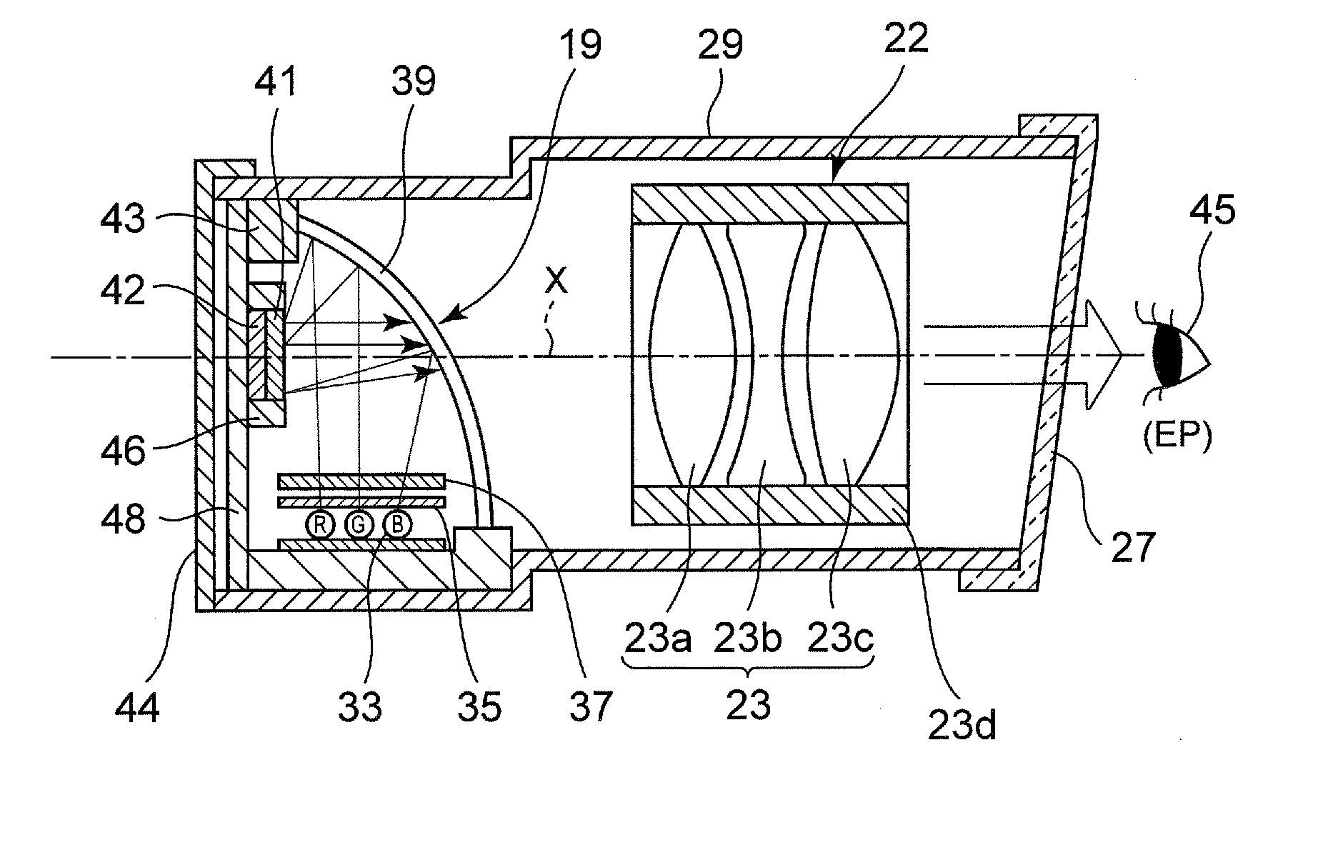
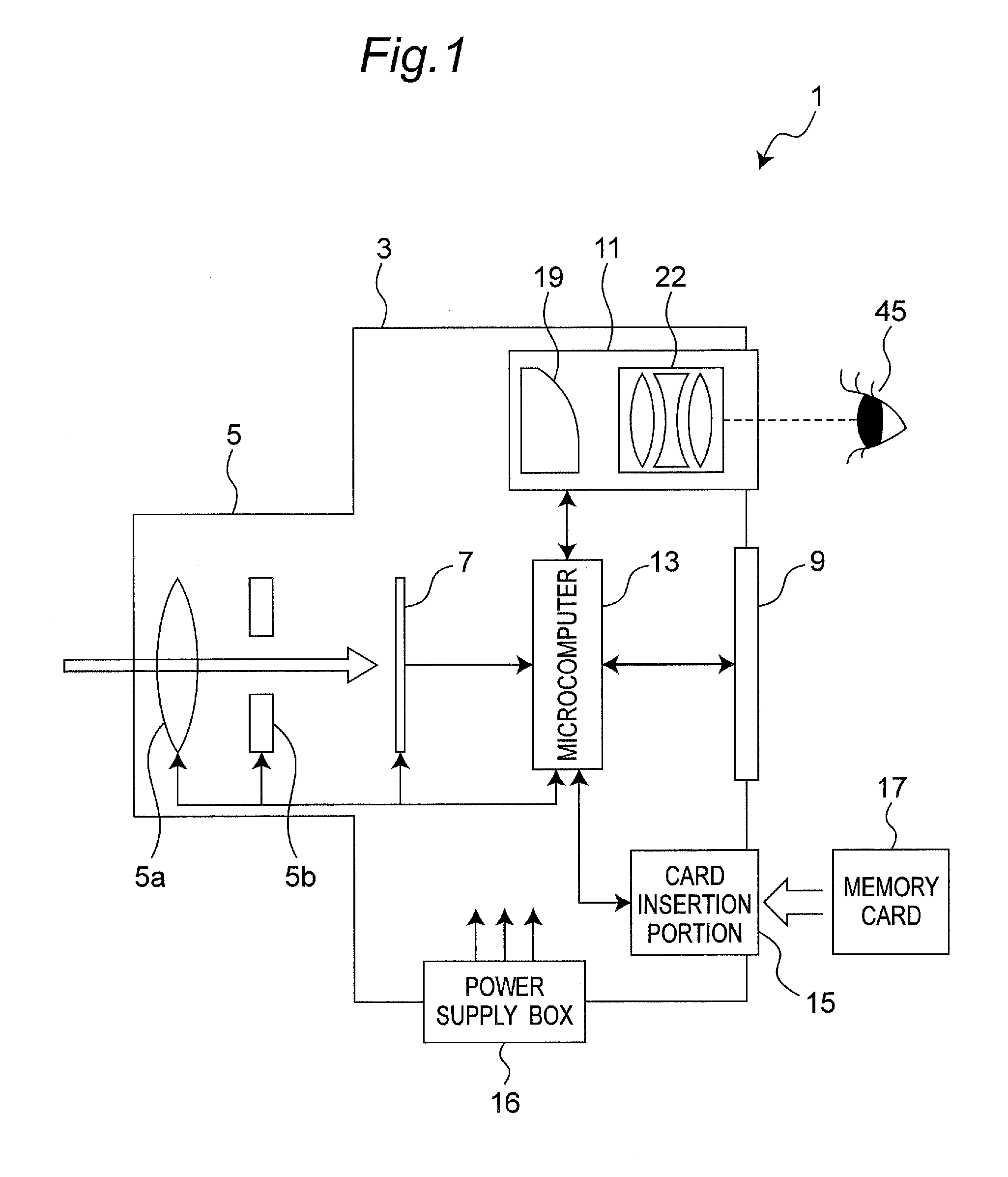
[0023]An eyepiece lens system, a finder optical system including the eyepiece lens system, an electronic viewfinder including the finder optical system, and an imaging apparatus including the electronic viewfinder according to an embodiment will be described below with reference to the accompanying drawings.

[0024]Note that the embodiment described below merely exemplifies an eyepiece lens system, and the like, to embody the technical idea and thus an eyepiece lens system, and the like, of the present embodiment are not restricted or limited to those described below. Particularly, in the present specification the elements recited in claims are not restricted to those in the embodiment. Note that a size, a positional relationship, and the like, of members shown in the drawings may be exaggerated to clarify the description.

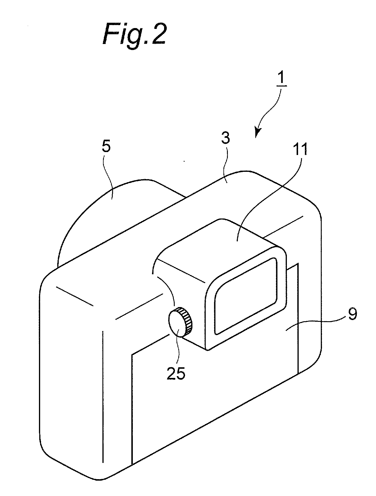
[0025]FIG. 1 shows a schematic internal circuit block configuration of an imaging apparatus, FIG. 2 shows an external configuration of the imaging apparatus as viewe...

embodiment 2

[0107]Next, the embodiment 2 will be described. Note that configuration of an imaging apparatus of the embodiment 2 is substantially same as that of the embodiment 1. Difference points are parameters of lenses cofiguring the electronic viewfinder 11. These difference points are caused by the diagonal length of the reflective LCD 19 being substantially a half of that of the embodiment 1. Concretely, because the reflective LCD 19 is substantially a half of that of the embodiment 1, it is necessary that magnification of image in finder optical system 22 needs to be twice as big as that of the embodiment 1 so that an observer can see an image with the same size via the electronic viewfinder 11. But, when making magnification of image in finder optical system 22 times, the above described various aberrations can appear more frequently. In the embodiment 2, parameter of lenses 23a, 23b, and 23c of the eyepiece lens system 23, and the like, are determined so that the above described variou...


PUM


Abstract

An eyepiece lens system for an electronic viewfinder, usable to be disposed on an optical axis between a reflective LCD of the viewfinder and a last optical surface of the viewfinder, the eyepiece lens system comprising: a first lens having a positive refractive index; a second lens having a negative refractive index; and a third lens having a positive refractive index, wherein the first lens, the second lens, and the third lens are disposed in this order from a side of the LCD to a side of the last optical surface, satisfying the conditions: 18 mm<f1<20 mm, −18 mm<f2<−16 mm, 18 mm<f3<20 mm, 19 mm<f<21 mm, and 0≦̸HH′ / f<+0.13 where f1 is a focal length of the first lens, f2 is a focal length of the second lens, f3 is a focal length of the third lens, f is a combined focal length of the first to the third lenses, and HH′ is distance in an optical axis direction between a rear principal point H and a front principal point H′.

Description

BACKGROUND[0001]1. Technical Field[0002]The technical field relates to an eyepiece lens system of an electronic viewfinder (EVF) which is a display apparatus that is mounted on imaging apparatuses such as television cameras, video cameras, and digital cameras and that is used to focus on a subject upon shooting or to observe the subject to determine a composition, a finder optical system including the eyepiece lens system, an electronic viewfinder including the finder optical system, and an imaging apparatus including the electronic viewfinder.[0003]2. Related Art[0004]An electronic viewfinder includes an LCD (liquid crystal display) and a finder optical system. The LCD displays, in the finder, a subject image on a liquid crystal display surface according to an image signal from an imaging device in an imaging apparatus. The LCD displaying the image display requires an illumination optical system that illuminates the LCD. In recent years, to meet a demand for saving space in mountin...

Claims


Application Information

Patent Timeline
Patent Type & Authority Applications(United States)
IPC IPC(8): G03B13/02G02B25/00
CPCG03B13/02G02B25/001
Inventor OGINO, YUSHINIWA, KUNIOYAMAZAKI, TAKAYUKI
Owner PANASONIC CORP
Learn More