Power source device and image forming apparatus

a technology of power source device and image forming apparatus, which is applied in the direction of power conversion system, electrographic process apparatus, instruments, etc., can solve the problems of increasing the number of its components, the inability to control output voltage, and the inability to substantially use high voltage output around the resonant frequency

Inactive Publication Date: 2010-04-29
OKI DATA CORP
View PDF3 Cites 26 Cited by
  • Summary
  • Abstract
  • Description
  • Claims
  • Application Information

AI Technical Summary

Benefits of technology

[0012]According to one aspect of the invention, a power source device includes: an oscillator generating a clock; a frequency division unit dividing the clock to output a pulse; a sequence generation unit generating an “N” number of sequences, in which each element has substantially the same occurrence rate, with respect to each switching of the pulse by synchronizing with the pulse; a frequency division ratio setting unit setting a frequency division ratio of the pulse; a switching element driven by the pulse; and a piezoelectric transformer outputting an alternating current high voltage from a secondary side thereof when a primary side thereof is intermittently applied with a voltage by the switching element. The generated sequence and the set frequency division ratio are compared to output the pulse of a fractional-M frequency and the pulse of a fractional-M+1 frequency. An average frequency division ratio of the pulse of the fractional-M frequency and the pulse of the fractional-M+1 frequency is determined by (M×α)+(M+1)×β / (α+β), where the α represents the number of the pulses of the fractional-M frequency and the β represents the number of the pulses of the fractional-M+1 frequency per unit time. The average frequency division ratio and the frequency division ratio become substantially equal to each other at a generation cycle of the sequence, and become approximated to each other in a period shorter than the sequence generation cycle.

Problems solved by technology

First, the related art power source device includes an analog circuitry, such as the VCO or the like, causing an increase in the number of its components.
Second, in a case where the high voltage output around resonant frequency of the piezoelectric transformer is used and where the output voltage is decreased by the load fluctuation, the output voltage cannot be controlled if the frequency of the output voltage is controlled to be lower than the resonant frequency.
Consequently, the high voltage output around the resonant frequency cannot be substantially used.
Consequently, the prioritization of rise time or leading edge time causes deterioration of the controllability around the resonant frequency.
The prioritization of the controllability around the resonant frequency, on the other hand, causes prolongation of the rise time or leading edge time.
Finally, in a case where a control target voltage is relatively row, a circuit structure using an analog oscillator such as the VCO can be influenced by spurious frequency, causing difficulty of controlling the output voltage.

Method used


Image

  • Power source device and image forming apparatus
  • Power source device and image forming apparatus
  • Power source device and image forming apparatus

Examples


first embodiment

[0034]Referring to FIG. 3, an image forming apparatus 1 including a power source device 70 according to a first embodiment of the present invention is illustrated in a schematic block diagram.

[0035]The image processing apparatus 1 is, for example, a multi-color image forming apparatus employing an electrophotographic method, and includes a black development device 2K, a yellow development device 2Y, a magenta development device 2M, and a cyan development device 2C detachably disposed thereto (K, Y, M, and C hereafter represent colors of black, yellow, magenta, and cyan, respectively). Photosensitive drums 32K, 32Y, 32M, and 32C are uniformly charged by respective charging rollers 36K, 36Y, 36M, and 36C contacting the respective photosensitive drums 32K, 32Y, 32M, and 32C. The charged photosensitive drums 32K, 32Y, 32M, and 32C form latent images thereon by light emitted from a black light emitting element (hereafter referred to as LED) head 3K, a yellow LED head 3Y, a magenta LED he...

second embodiment

[0143]An image forming apparatus and a control circuit according to a second embodiment of the present invention are respectively similar to the image forming apparatus 1 illustrated in FIG. 3 and the control circuit illustrated FIG. 4 according to the first embodiment while a power source device 70A according to the second embodiment differs from the power source device 70 illustrated in FIG. 2 according to the first embodiment. The power source device 70A that differs from the power source device 70 of the first embodiment will be described, and like components including the image forming apparatus and the control circuit will be given the same reference numerals as above and description thereof will be omitted.

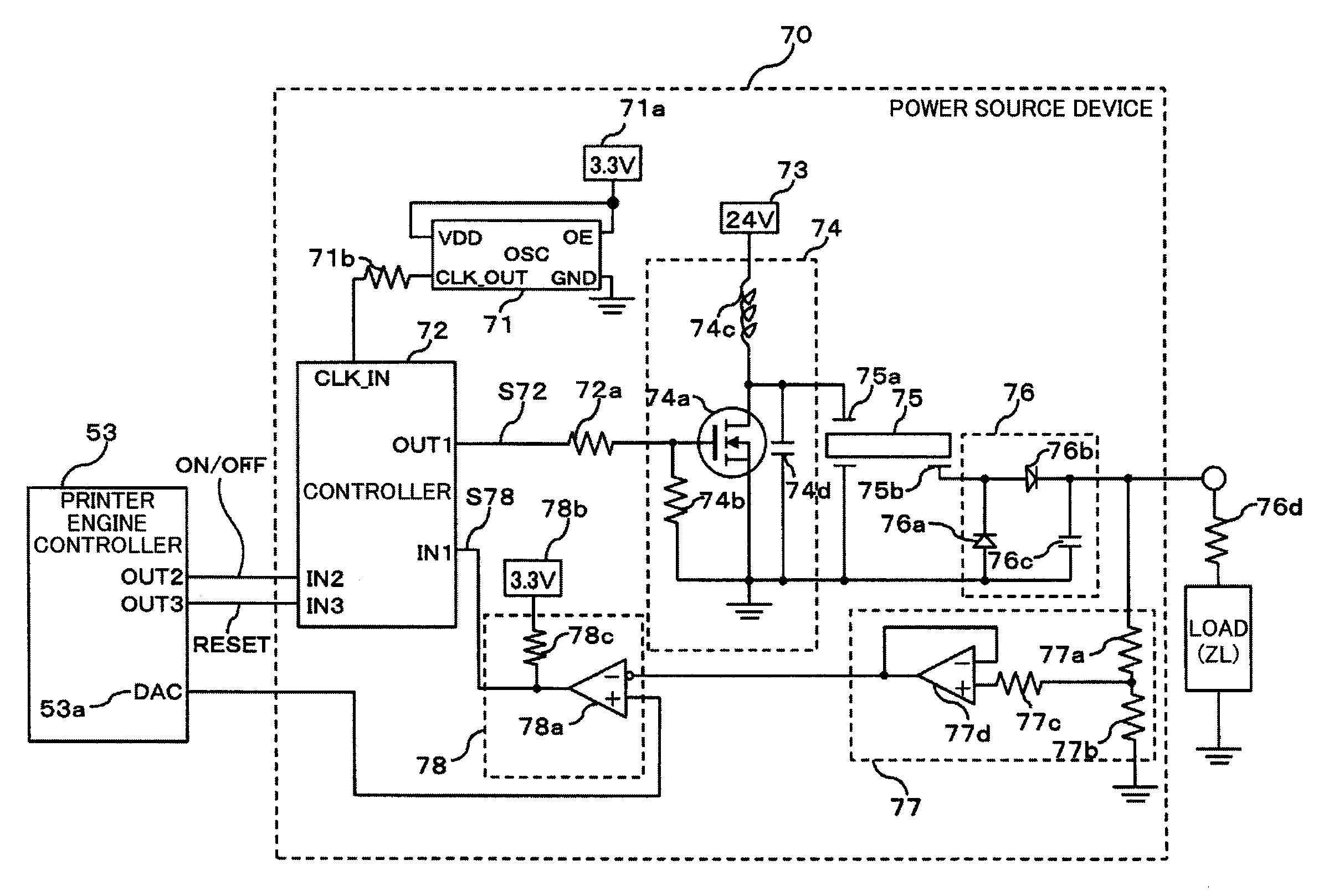
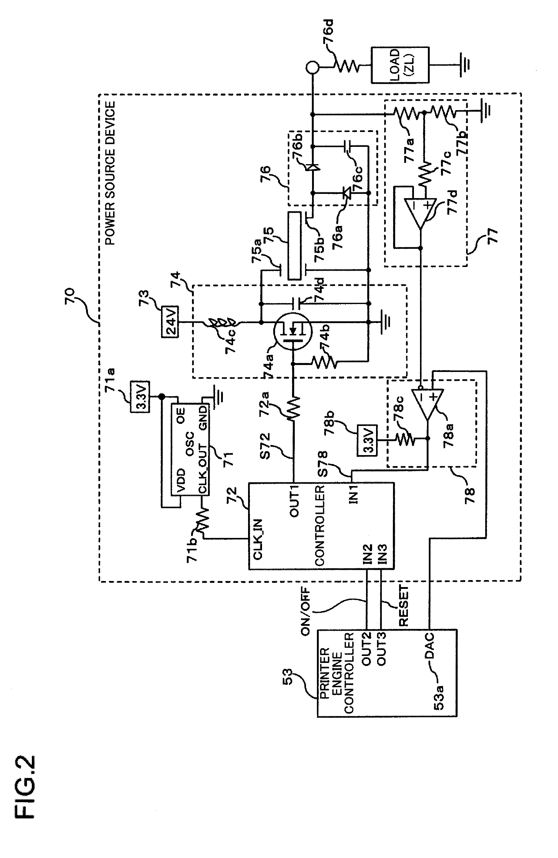
[0144]Referring to FIG. 11, the power source device 70A is illustrated in a schematic diagram, and like components are given the same reference numerals as the power source device 70 of the first embodiment, and the description thereof is omitted.

[0145]The power source devi...

third embodiment

[0173]An image forming apparatus, a control circuit, and a power source device according to a third embodiment are substantially similar to the image forming apparatus 1 of FIG. 3, the control circuit of FIG. 4, and the power source device 70 of FIG. 1 and FIG. 2 according to the first embodiment described above except for a controller 72B. A description is now gevin of the controller 72B of the third embodiment

[0174]Referring to FIG. 14, the controller 72B disposed inside the power source device 70 according to the third embodiment of the present invention is illustrated in a schematic diagram. Components similar to the first embodiment are given the same reference numerals.

[0175]The controller 72B of the third embodiment includes a frequency division ratio setting unit (e.g., a 6-bit counter) 87B and a sequence generator (e.g., a 6-bit pseudo random number generator) 92B instead of the 6-bit counter 87 and the 6-bit sequence generator 92 in the controller 72 of the first embodimen...


PUM


Abstract

A power source device includes an oscillator generating a clock, a frequency division unit dividing the clock to output a pulse, a sequence generation unit generating sequences “N” with respect to each switching of the pulse, a frequency division ratio setting unit setting frequency division ratio, a switching element driven by the pulse, and a piezoelectric transformer outputting alternating high voltage from a secondary-side when a primary-side is applied with voltage. The generated sequence and the set frequency division ratio are compared to output the pulses of fractional-M, −M+1 frequencies. An average frequency division ratio of the pulses of fractional-M, −M+1 frequencies determined by (M×α)+(M+1)×β/(α+β), where α and β respectively represent the number of pulses of “M” and “M+1” per unit time. The average frequency division ratio and frequency division ratio become equal at a sequence generation cycle and approximated in a period shorter than the sequence generation cycle.

Description

BACKGROUND OF THE INVENTION[0001]1. Field of the Invention[0002]The present invention relates to a power source device including a piezoelectric transformer and to an image forming apparatus such as an electrophotographic image forming apparatus using the power source device.[0003]2. Description of Related Art[0004]As a related art power source device for an image forming apparatus employs an electrophotographic method as described in such as Patent Document 1, a piezoelectric transformer has been known for generating the high voltage by an input of the low voltage using a resonance phenomenon of a piezoelectric vibrator and controlling the piezoelectric transformer using an output signal of a voltage-controlled oscillator (hereafter referred to as VCO) to output the high voltage.[0005]Patent Document 1: Japanese Un-examined Patent Application Publication No. 2006-91757[0006]Such a related art power source device, however, has various drawbacks as follows.[0007]First, the related ar...

Claims


Application Information

Patent Timeline
Patent Type & Authority Applications(United States)
IPC IPC(8): G03G15/00H02M5/00
CPCG03G15/80G03G15/1675
Inventor KOSAKA, TORUYAJI, MASAOHAGIWARA, AKIRA
Owner OKI DATA CORP
Why Eureka
Try Eureka