
Flexible linking piece for stabilising the spine

a flexible linking and spine technology, applied in the field of connecting members, can solve the problems of bending and bending of the spine, and achieve the effect of reducing the risk of fracture and bending

Inactive Publication Date: 2010-05-06
ZIMMER SPINE SAS
View PDF99 Cites 11 Cited by
  • Summary
  • Abstract
  • Description
  • Claims
  • Application Information

AI Technical Summary

Benefits of technology

"The patent describes a connecting member that allows for the maintenance of the spacing between anchor members while also allowing for relative movement between them. The connecting member is made up of two rigid parts that are fixed into the anchor members and a flexible connecting body that interconnects the rigid parts. The connecting member is designed to be easily assembled and can be hot molded onto the anchor members. The system also includes at least two anchor members and a connecting member that interconnects them, allowing for relative mobility between the vertebrae. The technical effect of this invention is to provide a more flexible and elastically deformable connecting member that allows for the movement of anchor members while maintaining their spacing."

Problems solved by technology

Such assemblies hold the vertebrae correctly relative to each other; however, they considerably stiffen the spine in terms of bending.

Method used


Image

  • Flexible linking piece for stabilising the spine
  • Flexible linking piece for stabilising the spine
  • Flexible linking piece for stabilising the spine

Examples


Embodiment Construction

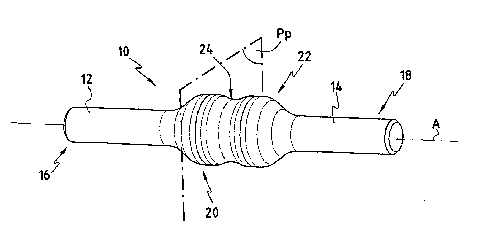
[0025]The various portions of a connecting member are described initially with reference to FIG. 1.

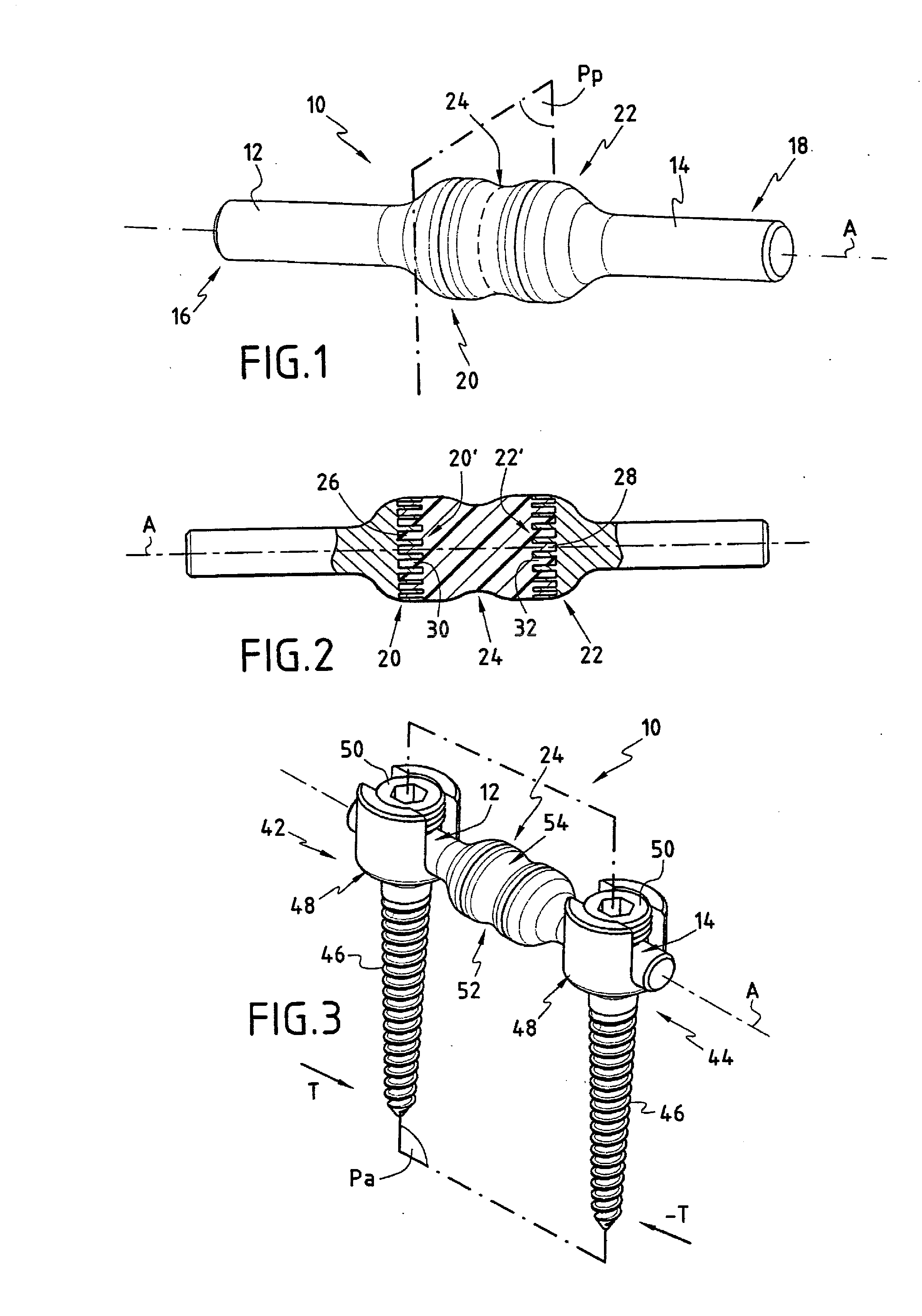
[0026]The connecting member 10 has two cylindrical rigid parts 12 and 14. Each rigid part 12, 14 has a fixing, first portion 16, 18 and a fastening, second portion 20, 22 forming an enlargement. The facing fastening portions 20 and 22 are connected together by a connecting body 24 so that the rigid parts 12 and 14 are in axial alignment. The connecting member 10 is therefore circularly symmetrical about the axis A.

[0027]How the two rigid parts 12 and 14 are fastened together is described below with reference to FIG. 2.

[0028]The connecting body 24 is a plastics material body obtained by polymerization. The material of the body is chosen from materials which are more elastically deformable than the material of said rigid parts 12, 14 and, most importantly, whose elastic properties are of the same order of magnitude as those of the posterior ligaments that hold the spine together.

[0029]Or...


PUM


Abstract

Embodiments described herein relate to a connecting member for maintaining the spacing between at least two anchor members screwed into vertebrae and methods for stabilizing the spine using a connecting member. One embodiment of a connecting member can include a first rigid portion formed of a first material, a second rigid portion formed of the first material and a connecting body comprising a second material that is more elastically deformable than the first material.

Description

CROSS-REFERENCE TO RELATED APPLICATIONS[0001]This application is a continuation of and claims priority under 37 CFR 1.53(b) to U.S. patent application Ser. No. 10 / 333,881, filed Jan. 24, 2003, entitled “Flexible Linking Piece for Stabilising the Spine” by inventors Regis LeCouedic and Denis Pasquet, which claims priority under 35 U.S.C. 371 to International Application No. PCT / FR01 / 02426, filed Jul. 25, 2001, entitled “Flexible Linking Piece for Stabilising the Spine” by inventors Regis LeCouedic and Denis Pasquet, which claims benefit of priority to French Application No. 00 / 09706 entitled “Flexible Linking Piece for Stablising the Spine” by inventors Regis LeCouedic and Denis Pasquet, filed Jul. 25, 2000, all of which are incorporated herein by reference.TECHNICAL FIELD[0002]This disclosure relates to a connecting member for maintaining the spacing between at least two anchor members which are interconnected by said connecting member.BACKGROUND[0003]Systems for stabilizing the ver...

Claims


Application Information

Patent Timeline
Patent Type & Authority Applications(United States)
IPC IPC(8): A61B17/70A61B17/88
CPCA61B17/7004A61B17/7031A61B17/7032
Inventor LE COUEDIC, REGISPASQUET, DENIS
Owner ZIMMER SPINE SAS
Learn More