Installation for filling containers

a technology for installing containers and filling containers, which is applied in the direction of filling device cleaning, packaging goods type, liquid bottling, etc., can solve the problems of complex structure of rotary gaskets, rotary gasket wear, and the need for rotary gaskets to complicate the installation structur

Inactive Publication Date: 2002-01-01
SERAC GROUP
View PDF6 Cites 34 Cited by
  • Summary
  • Abstract
  • Description
  • Claims
  • Application Information

AI Technical Summary

Benefits of technology

Thus, during the filling stage, the positioning means are actuated so as to maintain the lid spaced apart from the edge of the tank. In this position, the lid is prevented from rotating relative to the frame. The feed pipe can thus be fixed rigidly to the lid without it being necessary to use a rotary gasket. In addition, when the lid is in this position, the tank is naturally in communication with the ambient atmosphere. For the cleaning stage, the positioning means are actuated so that the lid closes off the tank. The tank can then be cleaned by injecting the cleaning substance under a high pressure, thereby facilitating proper cleaning of the tank.

Problems solved by technology

The need for a rotary gasket complicates the structure of the installation.
In addition, the rotary gasket is subject to wear, and the duct connecting the valve to the circuit for dispensing the cleaning substance must also be connected to the rotary gasket, and so the rotary gasket is of complex structure.

Method used


Image

  • Installation for filling containers
  • Installation for filling containers

Examples


Embodiment Construction

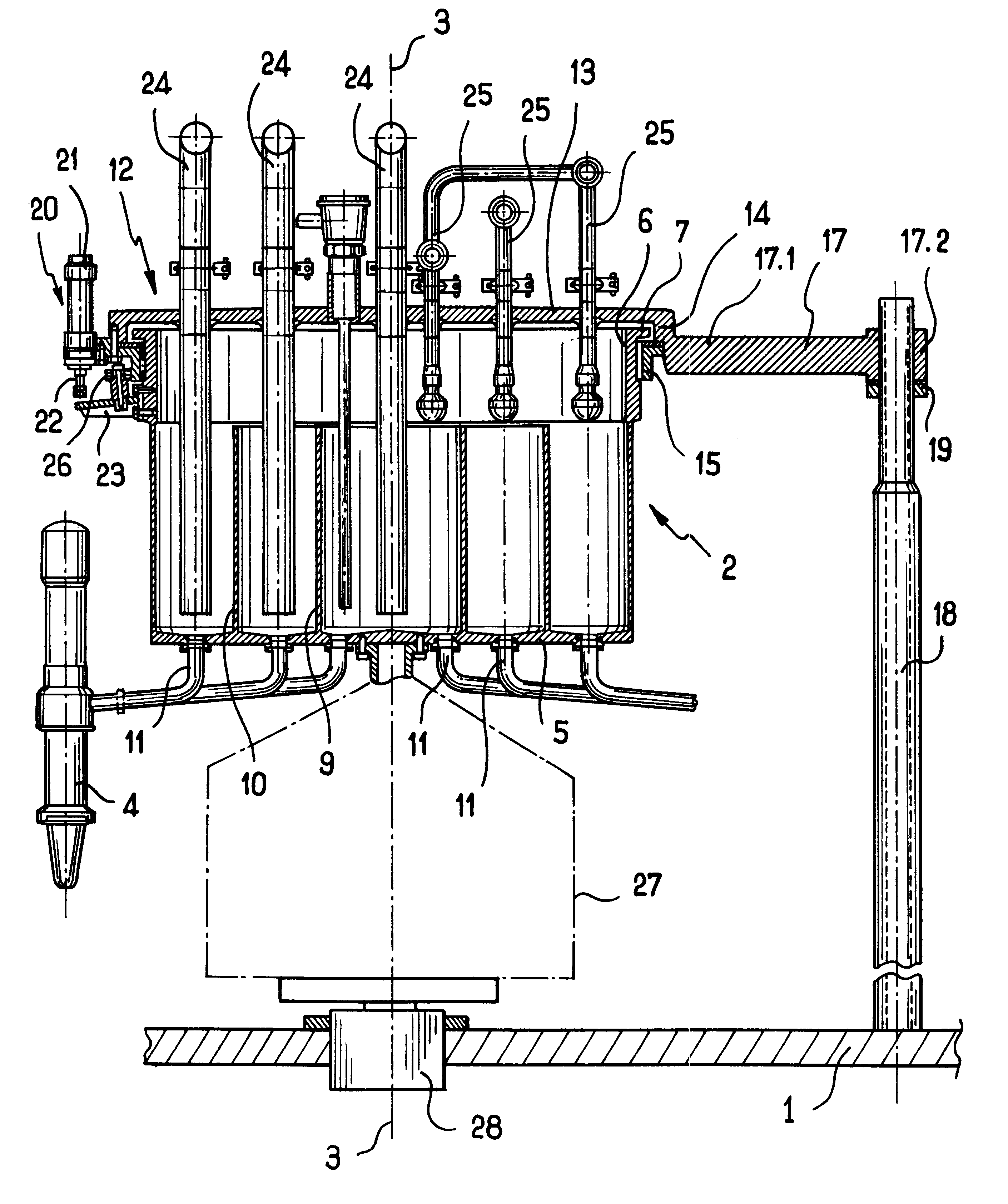
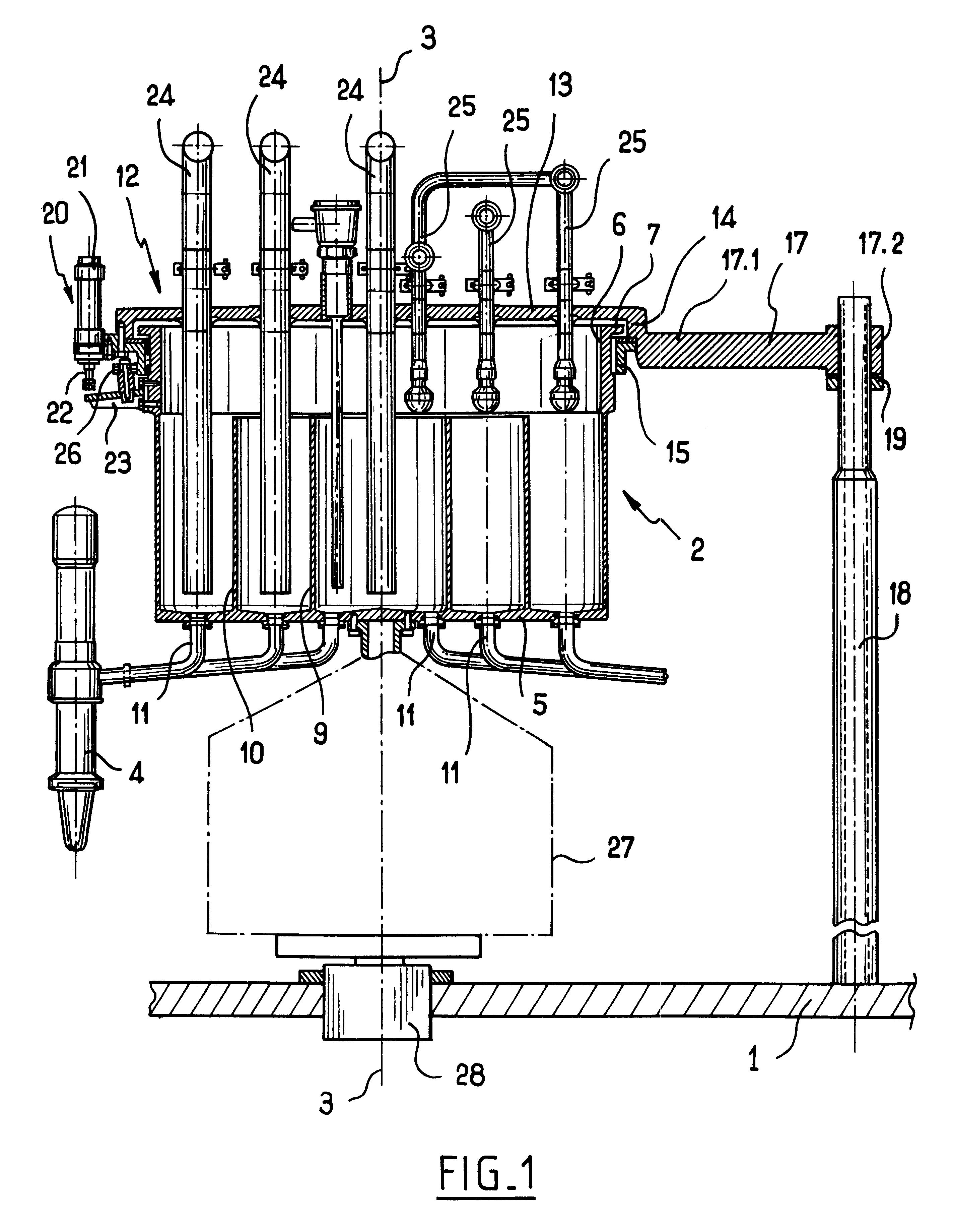
The filling installation of the invention includes a fixed frame 1 on which a tank given overall reference 2 is mounted via a structure 27 represented in chain-dotted lines and carried by a bearing 28 so as to rotate about an axis 3. The tank 2 is part of a filling platform of the carrousel type, and it is connected to filling nozzles 4 that are known per se, only one of which is shown in the figure.

The tank 2 is of cylindrical shape and it comprises a bottom 5 and a top opening 6 opposite from the bottom 5, and an annular rim 7 adjacent to the opening 6 and projecting outwards.

Two partitions 9 and 10 that are of cylindrical shape and that are centered on the axis 3 extend inside the tank 2, and they subdivide said tank into three compartments, the bottoms of which receive ducts 11 that open out in said bottoms and that are selectively connected to filling nozzles 4.

The installation includes a lid designated by overall reference 12 and covering the top portion of the tank 2.

The lid ...


PUM

PropertyMeasurementUnit
structureaaaaaaaaaa
pressureaaaaaaaaaa
weightaaaaaaaaaa

Abstract

A filling installation comprising a fixed frame, a tank mounted on the fixed frame so as to rotate about an axis, and a lid associated with the tank and provided with a feed pipe, positioning means being fixed to the lid, and being mounted on the fixed frame to slide parallel to the axis of rotation between a position in which the lid is applied against an edge of the tank so as to close off said tank and a position in which the lid is spaced apart from the edge of the tank.

Description

The present installation relates to an installation for filling containers, such an installation serving, for example, in a bottling line.A filling installation generally includes a filling platform of the carrousel type which is mounted to rotate about an axis on a fixed frame, and it continuously fills containers conveyed along the bottling line. To this end, it includes a tank to which filling nozzles are connected.In sterile filling installations, i.e. installations in which filling is performed without any germs entering the containers during the various steps of packaging the substance, a lid is fixed to the tank in sealed manner. The lid is provided with a valve which is controlled to put the tank in communication with the ambient atmosphere, as maintained in a sterile state, during the container-filling stage, and with a circuit for dispensing a cleaning substance during a periodic cleaning stage.The filling liquid is fed to the tank via a pipe having one end fixed to the li...

Claims


Application Information

Patent Timeline
Patent Type & Authority Patents(United States)
IPC IPC(8): B67C3/02B67C3/22B67C3/00B67C3/04B67C7/00
CPCB67C3/001B67C3/22B67C3/04
Inventor DUMARGUE, GUY
Owner SERAC GROUP
Why Eureka
Try Eureka