Display Apparatus

a display device and display device technology, applied in the field of display devices, can solve the problems of attracting much attention, limiting the development of new display devices, the limitation of slimming display devices, and the limitation of reducing the thickness of lcd devices or changing the design

Active Publication Date: 2012-12-27
LG DISPLAY CO LTD
View PDF2 Cites 41 Cited by
  • Summary
  • Abstract
  • Description
  • Claims
  • Application Information

AI Technical Summary

Benefits of technology

[0017]An aspect of the present invention is directed to provide a display device which can maintain a space between a lower substrate and a portion of an upper substrate with a transmitting hole formed therein, in an atmospheric pressure state.

Problems solved by technology

However, among such flat panel display devices, LCD devices are easily manufactured, have good drivability of drivers, realize a high-quality image, and thus are attracting much attention.
Due to these reasons, there are limitations in slimming display devices and developing the new designs of the display devices.
As described above, display devices of the related art necessarily use the front set cover and rear set cover as well as the lower case and front case, and consequently, there are limitations in reducing the thicknesses of LCD devices or changing the designs thereof.
Due to this reason, the thicknesses of display devices inevitably become thicker, and moreover, the border widths of the display devices enlarge.
In addition, it is difficult to realize various innovative designs due to a step height in a border portion.
Due to this reason, the border width of a screen in the notebook computers increases further, and moreover, due to the step height of a border portion, it is difficult to develop various innovative designs.

Method used


Image

  • Display Apparatus
  • Display Apparatus
  • Display Apparatus

Examples


first embodiment

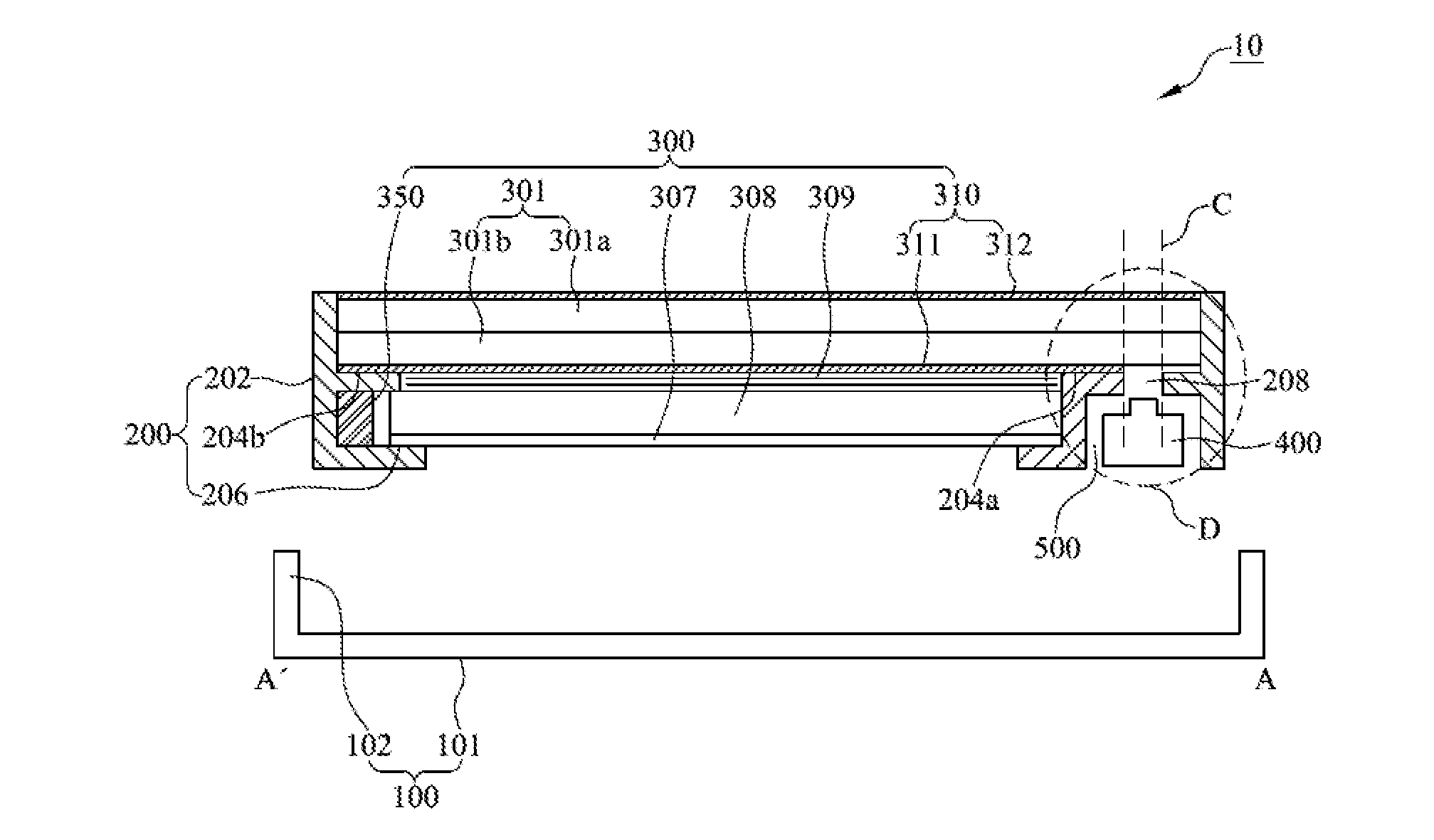
[0065]That is, FIG. 3 is a detailed sectional view of the display device according to the present invention, and is an exemplary view specifically illustrating a sectional surface of the panel 301.

[0066]The panel 301 includes the upper substrate 301a, the lower substrate 301b, and the liquid crystal layer formed between the upper substrate 301 and the lower substrate 301b.

[0067]The lower substrate 301b is a driving element array substrate. Although not specifically shown in the drawing, a plurality of pixels are formed at the lower substrate 301b, and a thin film transistor and a driving element are formed at each of the pixels.

[0068]The upper substrate 301a is a color filter substrate, and a color filter layer for realizing color is formed at the upper substrate 301a.

[0069]In the lower substrate 301b and upper substrate 301a, moreover, a plurality of pixel electrodes and common electrodes are formed and an alignment layer for aligning liquid crystal molecules of the liquid crysta...

second embodiment

[0093]The display device according to the present invention is characterized in that a solid transmitting material 301t is formed in a space between the camera hole 208 and the transmitting hole 301g that is maintained in an atmospheric pressure state, in a space between the upper substrate 301a and the lower substrate 301b.

[0094]A plurality of column spacers 301s and 301h are formed in the active area or the first inactive area, and then the transmitting material 30 lt may be formed. Alternatively, the transmitting material 301t may be formed simultaneously with the column spacers 301s and 301h.

[0095]Herein, the transmitting material 301t may be formed of a material having a refractive index similar to that of a glass which forms the upper substrate 301a and the lower substrate 301b, and remove a spectrum type of concentric circle by reducing the diffraction of light transmitted through the transmitting hole 301g.

[0096]However, only a glass is not used as the transmitting materi...

third embodiment

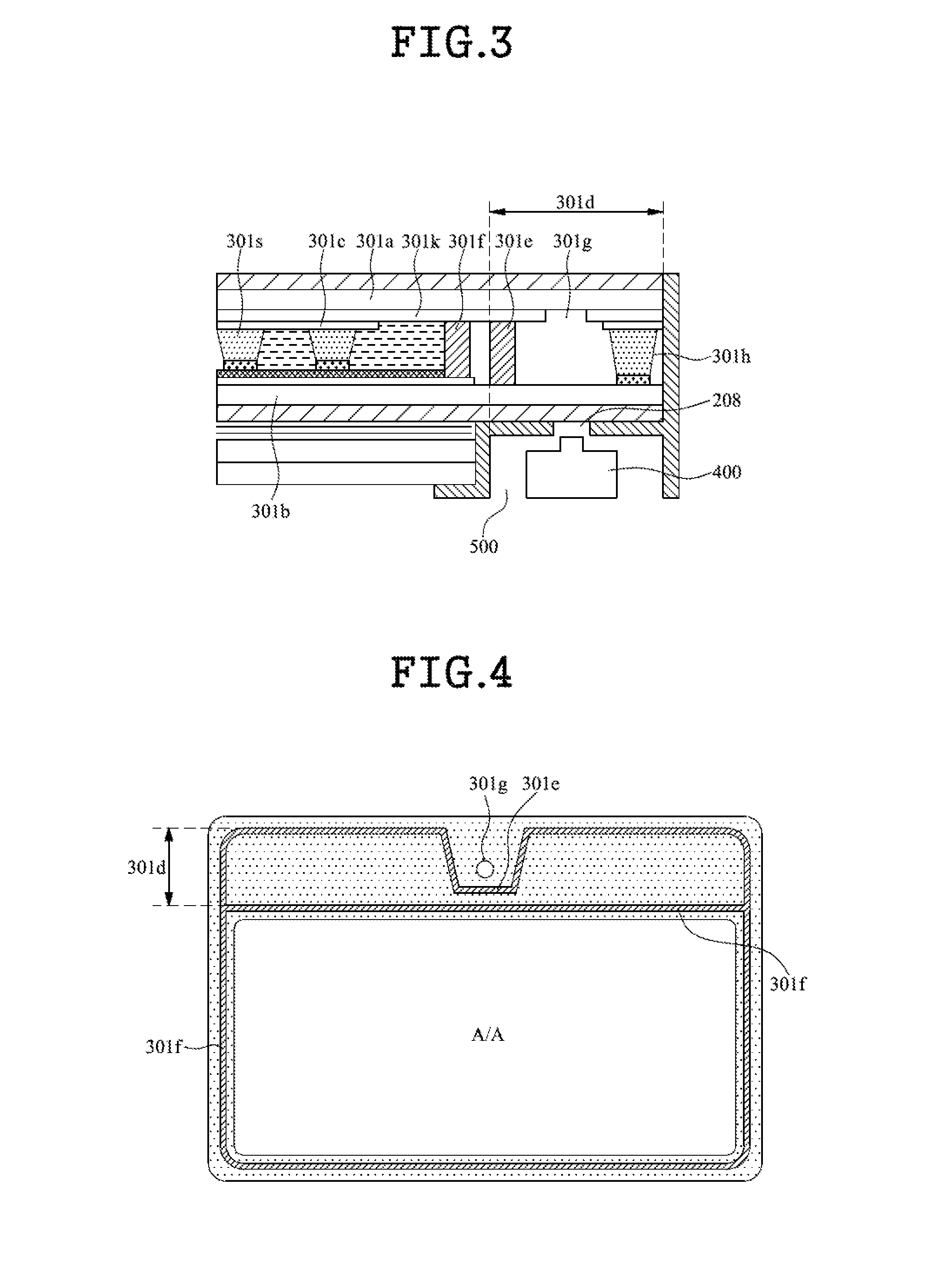
[0110]The display device of the third embodiment is characterized in that the first inactive area seal 301e is formed to surround only a portion of the first inactive area.

[0111]In the first embodiment and the second embodiment, a sealed space is formed to surround a portion of the first inactive area other than the periphery of the transmitting hole when the first inactive area seal 301e is being connected to a portion of the active area seal 301f. In the third embodiment, however, the first inactive area seal 301e is separately formed to be completely separated from the active area seal 301f.

[0112]To provide an additional description, in the first embodiment and the second embodiment, a portion of the first inactive area 301d other than the transmitting hole 301g is surrounded by the first inactive area seal 301e and the active area 301f to maintain a vacuum state, and only the periphery of the transmitting hole is exposed in an atmospheric pressure state. However, in the third e...


PUM

PropertyMeasurementUnit
refractive indexaaaaaaaaaa
atmospheric pressureaaaaaaaaaa
areaaaaaaaaaaa

Abstract

Disclosed is a display device which can maintain a space between a lower substrate and a portion of an upper substrate with a transmitting hole formed therein, in an atmospheric pressure state. The display device includes a display unit and a guide frame. The display unit includes a panel which is sealed, with liquid crystal being charged between an upper substrate and a lower substrate. The guide frame supports the display unit. The guide frame includes a guide side wall guiding a side surface of the panel, and a panel supporting part supporting the panel.

Description

CROSS-REFERENCE TO RELATED APPLICATIONS[0001]This application claims the benefit of the Korean Patent Application No. 10-2011-0061711 filed on Jun. 24, 2011, which is hereby incorporated by reference as if fully set forth herein.BACKGROUND[0002]1. Field of the Invention[0003]The present invention relates to a display device, and more particularly, to a borderless type display device with a built-in camera.[0004]2. Discussion of the Related Art[0005]Recently, flat panel display devices that can decrease a weight and a volume corresponding to the limitations of Cathode Ray Tubes (CRTs) are being developed. Liquid Crystal Display (LCD) devices, Plasma Display Panels (PDPs), Field Emission Display (FED) devices, and light emitting display devices are actively being researched as flat type display devices. However, among such flat panel display devices, LCD devices are easily manufactured, have good drivability of drivers, realize a high-quality image, and thus are attracting much attent...

Claims


Application Information

Patent Timeline
Patent Type & Authority Applications(United States)
IPC IPC(8): G02F1/1339G02F1/1333G03B30/00
CPCG06F1/1686G06F1/1637G02F1/1333G02F1/1335
Inventor PARK, JAEWOOBAEK, SEUNGJAE
Owner LG DISPLAY CO LTD
Why Eureka
Try Eureka