
Computing diagnostic explanations of network faults from monitoring data

a network fault and computer technology, applied in the field of network management and network fault diagnosis, can solve problems such as unsatisfactory generalization of the solution

Inactive Publication Date: 2010-05-06
TT GOVERNMENT SOLUTIONS
View PDF16 Cites 92 Cited by
  • Summary
  • Abstract
  • Description
  • Claims
  • Application Information

AI Technical Summary

Problems solved by technology

The problem is to determine the root causes of communication network faults based on network monitoring results, either given as a snapshot of the network state or as a continuous stream.
Additionally, the proposed solution is not fully general in that it does not deal with the issue of possibly faulty monitoring results.

Method used


Image

  • Computing diagnostic explanations of network faults from monitoring data
  • Computing diagnostic explanations of network faults from monitoring data
  • Computing diagnostic explanations of network faults from monitoring data

Examples


Embodiment Construction

[0017]Diagnosis of network faults is a problem of reasoning in the face of missing information concerning the state of the network. With incomplete information, a network fault diagnosis is likely to have some ambiguity, which leads to the secondary challenge of how to react appropriately in the face of the ambiguity. A proper network fault diagnosis capability must therefore have two requirements. First, the diagnoses must be complete with respect to the NMS's knowledge, meaning that the diagnoses must accurately describe the space of possibilities of all root causes that lead to the network state known to the NMS and its understanding of the network. Most known network fault diagnosis mechanisms produce either the single most likely cause or the single simplest cause that might explain the observed network state. While this approach might arrive at the correct diagnosis in many cases, it will necessarily give incorrect results in more complex cases. The ambiguity of the informatio...


PUM


Abstract

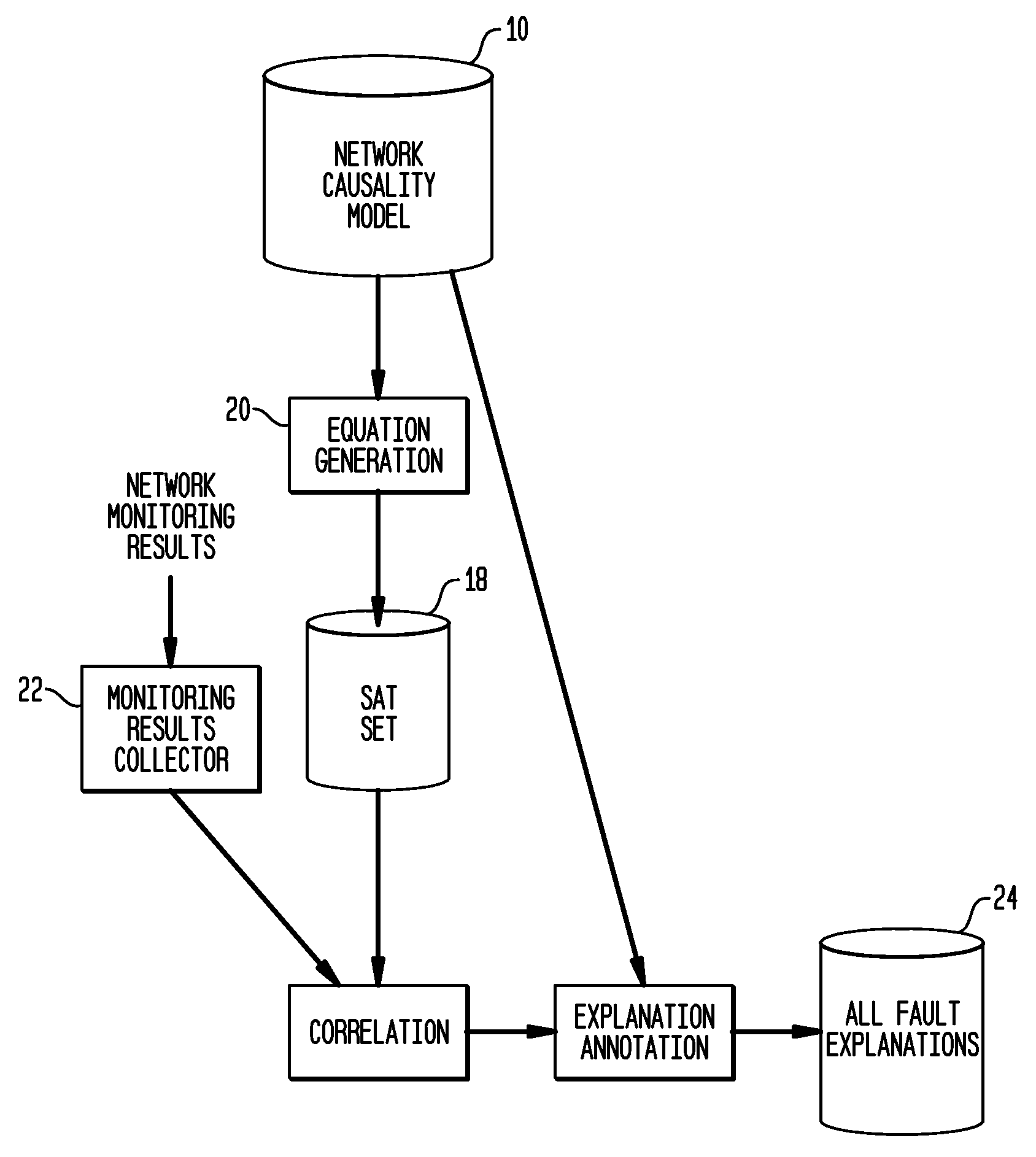
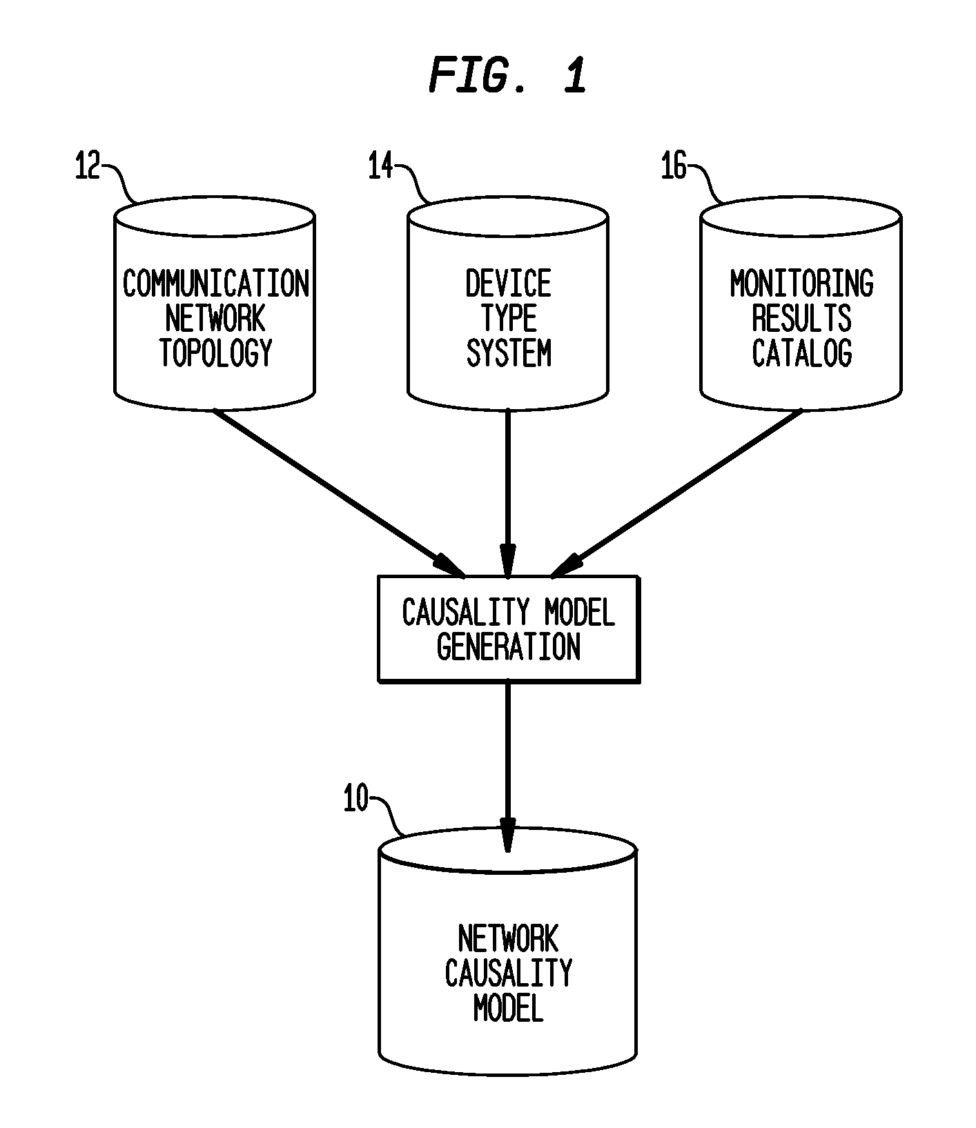
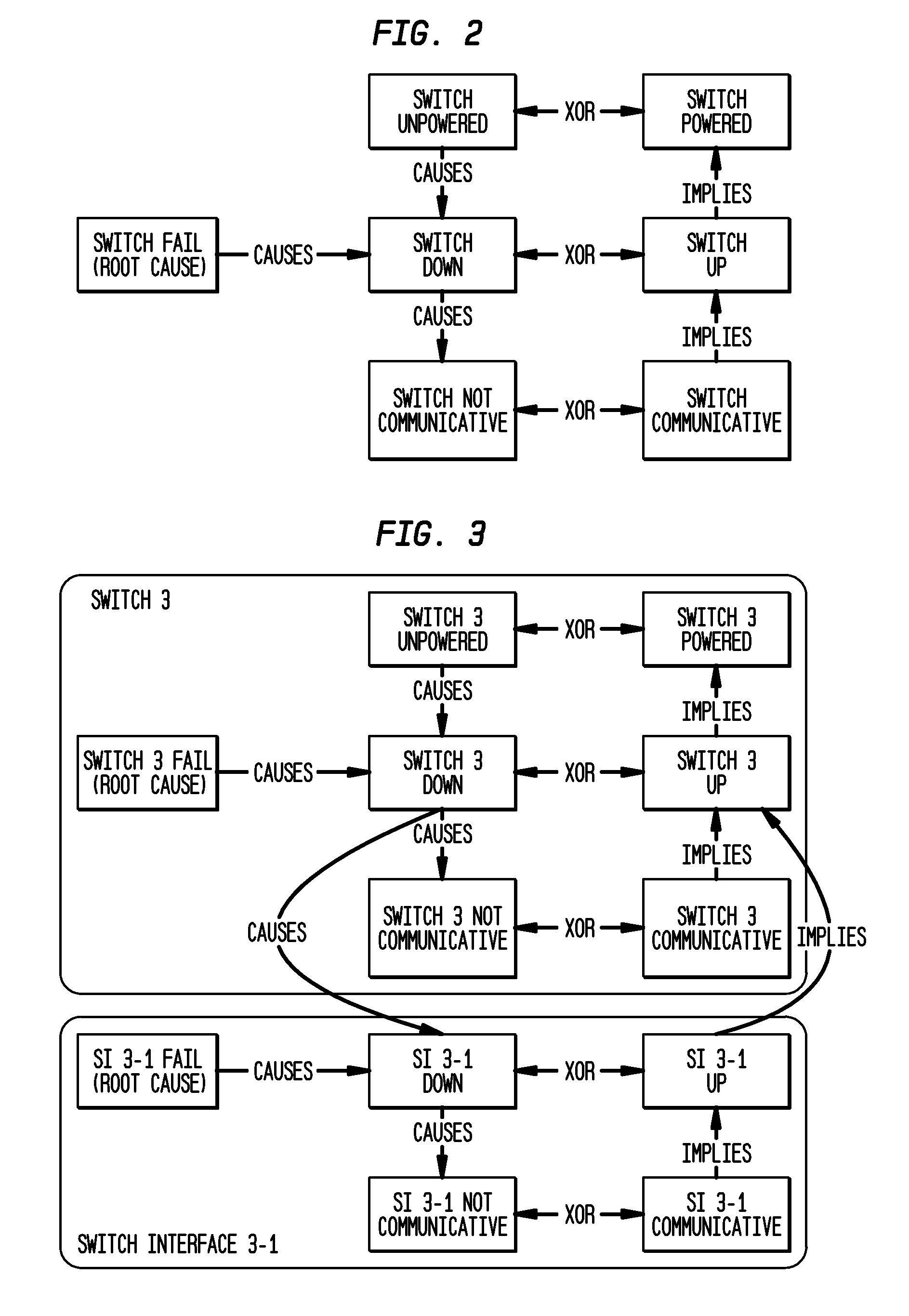
A system and method for network fault diagnosis in a network having network elements is presented. The method comprises creating a network causality model, generating Boolean expressions from the network causality model, converting the Boolean expressions into SAT sets, receiving network monitoring results, correlating these monitoring results with the SAT sets, and enumerating all possible diagnostic explanations of potential faults, properly annotated. Creating a network causality model can comprise creating, for each network element, an element-specific causality model, stitching together all network elements using the element-specific causality models and a network topology, retrieving monitoring state and propagation information, and generating the network causality model using the stitched together network elements and the monitoring state and propagation information. Stitching together network elements can comprise adding causes and implies dependency between appropriate network elements and / or adding and connecting reachable and not-reachable states. The network causality model can comprise network element states.

Description

CROSS REFERENCE TO RELATED APPLICATIONS[0001]The present invention claims the benefit of U.S. provisional patent application 61 / 094,272 filed Sep. 4, 2008, the entire contents and disclosure of which are incorporated herein by reference as if fully set forth herein.GOVERNMENT LICENSE RIGHTS[0002]This invention was made with Government support under DAAE07-03-9-F001 awarded by the Department of the Army. The Government has certain rights in this invention.FIELD OF THE INVENTION[0003]The present invention relates generally to network management and to network fault diagnosis.BACKGROUND OF THE INVENTION[0004]Diagnosing the causes of network faults is the first step in their correction, either by restoring the network to full operation or by reconfiguring the network to mitigate the impact of a fault. Fault diagnosis is relatively straightforward if one has information about the state of all active elements in the network. Unfortunately, such monitoring information is usually transmitte...

Claims


Application Information

Patent Timeline
IPC IPC(8): G06F15/173G06F11/07
CPCG06F11/0709G06F11/079H04L41/0631H04L41/16
Inventor BAKER, DONALDNODINE, MARIAN
Owner TT GOVERNMENT SOLUTIONS
Learn More