

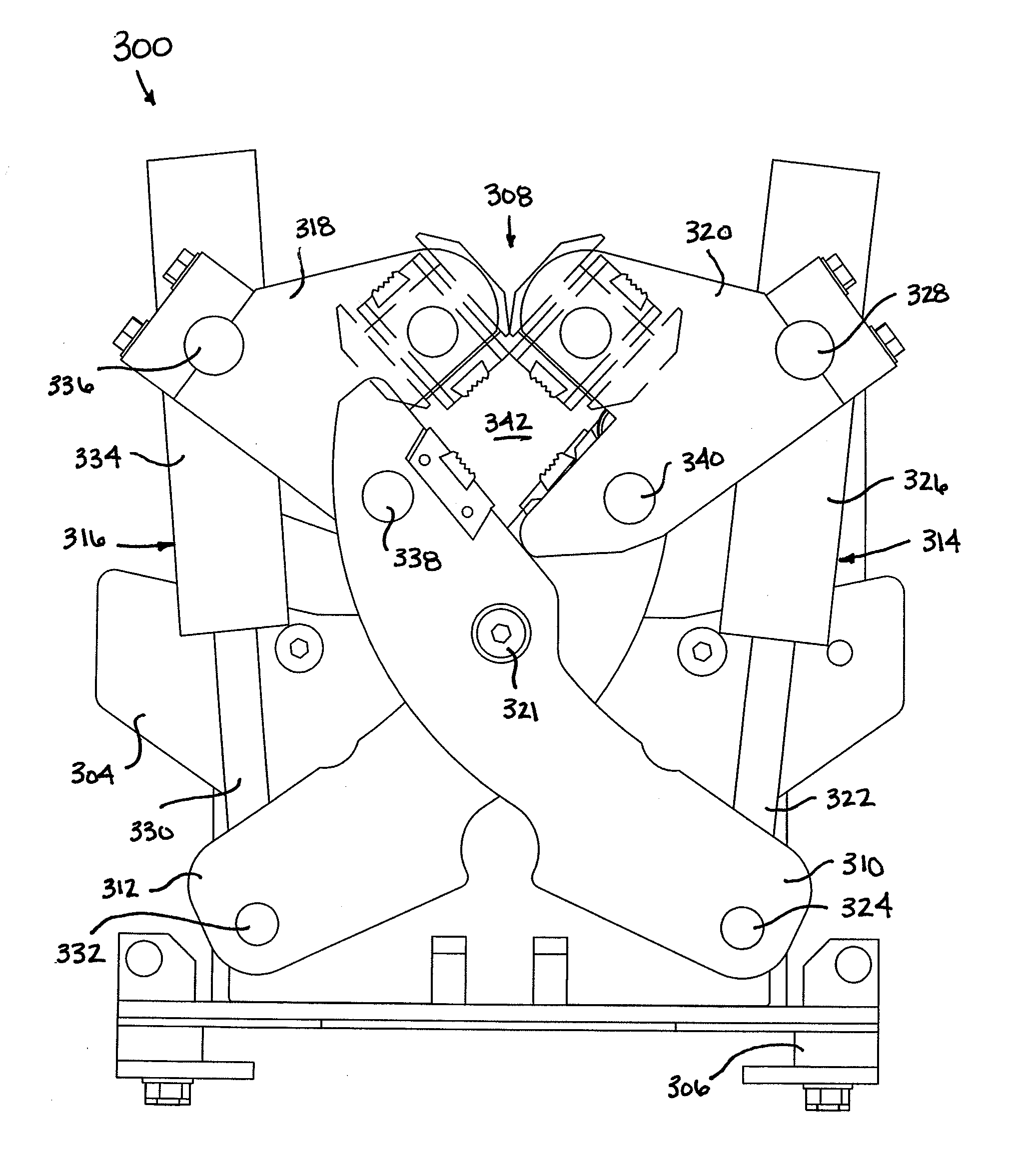
Vise for a directional drilling machine
a drilling machine and directional drilling technology, applied in the direction of drilling pipes, drilling rods, drilling casings, etc., can solve the problem of limited use of drill pipes in conjunction with the conventional jaw design
- Summary
- Abstract
- Description
- Claims
- Application Information
AI Technical Summary
Problems solved by technology
Method used
Image

Examples
Embodiment Construction
[0014]With reference now to the various figures in which identical elements are numbered identically throughout, a description of various exemplary aspects of the present invention will now be provided.
I. General Operation of the Vise Apparatus in Horizontal Drilling
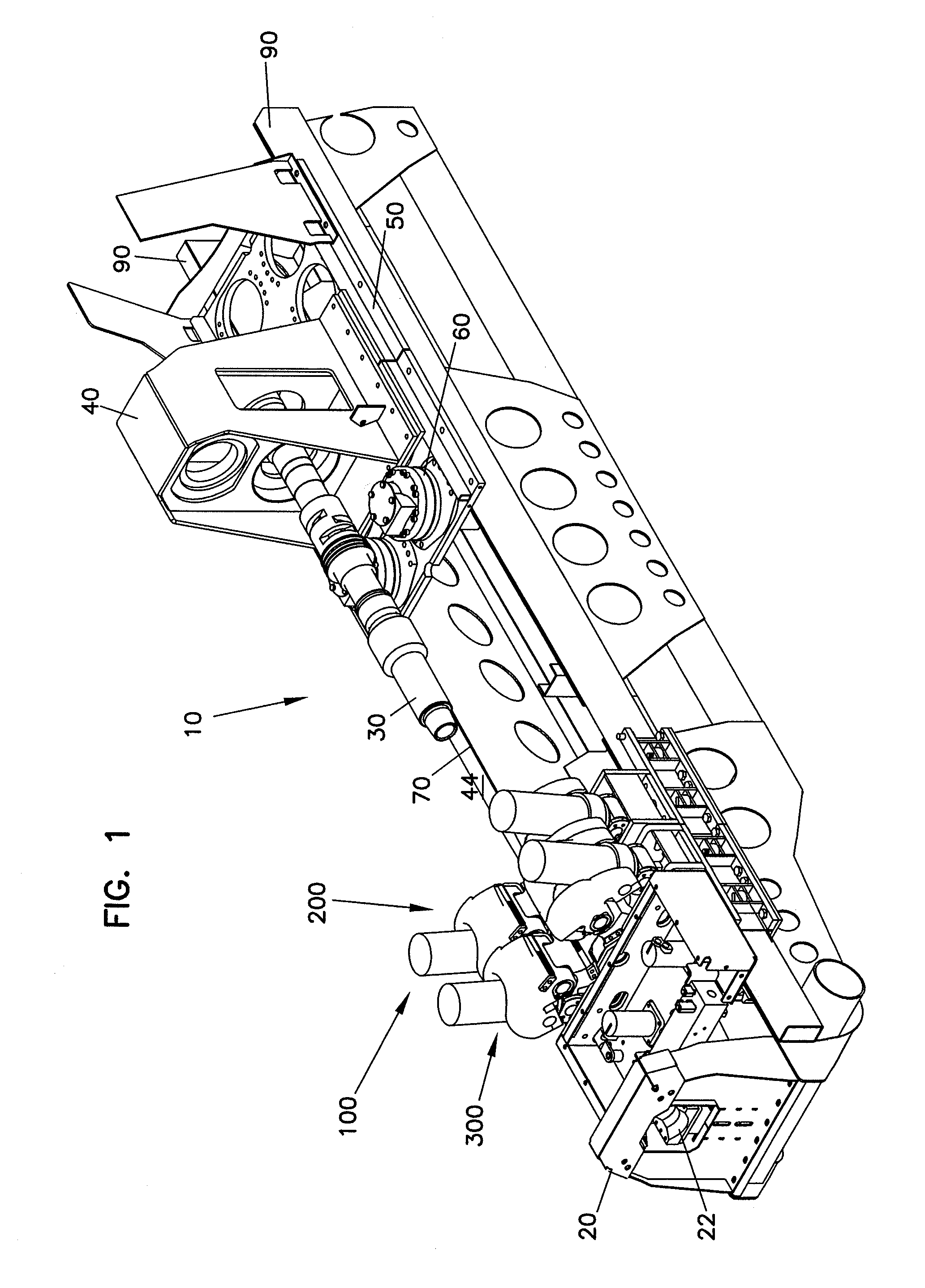
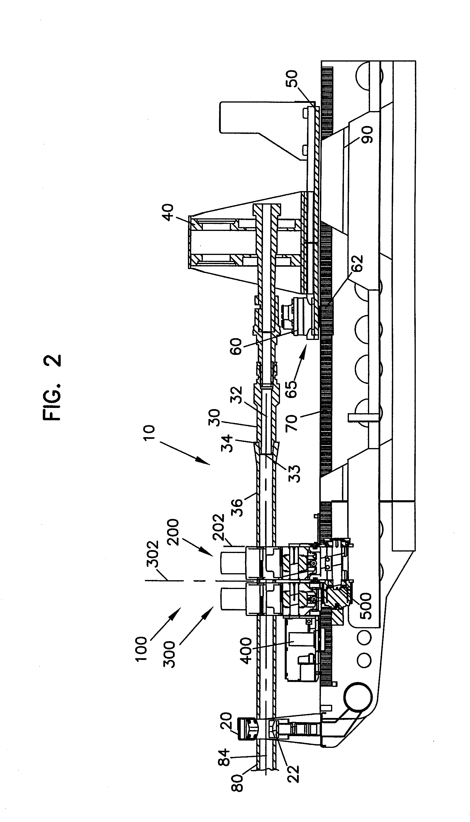
[0015]The present invention is directed to a vise apparatus for use on horizontal drilling machines. Horizontal drilling machines typically comprise a rotational drive mechanism, a longitudinal drive mechanism, a vise apparatus, a ground support, and a drill pipe storage / transfer apparatus. The drilling process involves threading together lengths of threaded drill pipe to form a drill string extending from the drilling machine though a bored hole and terminating at a drill bit assembly. The drill string transfers rotational torque and longitudinal thrust from the drive mechanisms to the drill bit assembly.
[0016]To begin drilling a bore, the drill bit assembly is located near the ground support of the horizontal drilling ...
PUM
 Abstract
Description
Claims
Application Information