Image forming apparatus

Inactive Publication Date: 2010-05-13
CANON KK
View PDF32 Cites 3 Cited by
  • Summary
  • Abstract
  • Description
  • Claims
  • Application Information

AI Technical Summary

Benefits of technology

[0006]The present invention is directed to an image forming apparatus capable of drying, for a short time, a medium or a transfer belt which gets wet through an image forming process while suppressing cost increase and upsizing of the apparatus.

Problems solved by technology

However, when the supply chamber is provided between rollers as described above, a size and cost of the apparatus may be increased.

Method used


Image

  • Image forming apparatus
  • Image forming apparatus
  • Image forming apparatus

Examples


Embodiment Construction

[0017]Various exemplary embodiments, features, and aspects of the invention will be described in detail below with reference to the drawings.

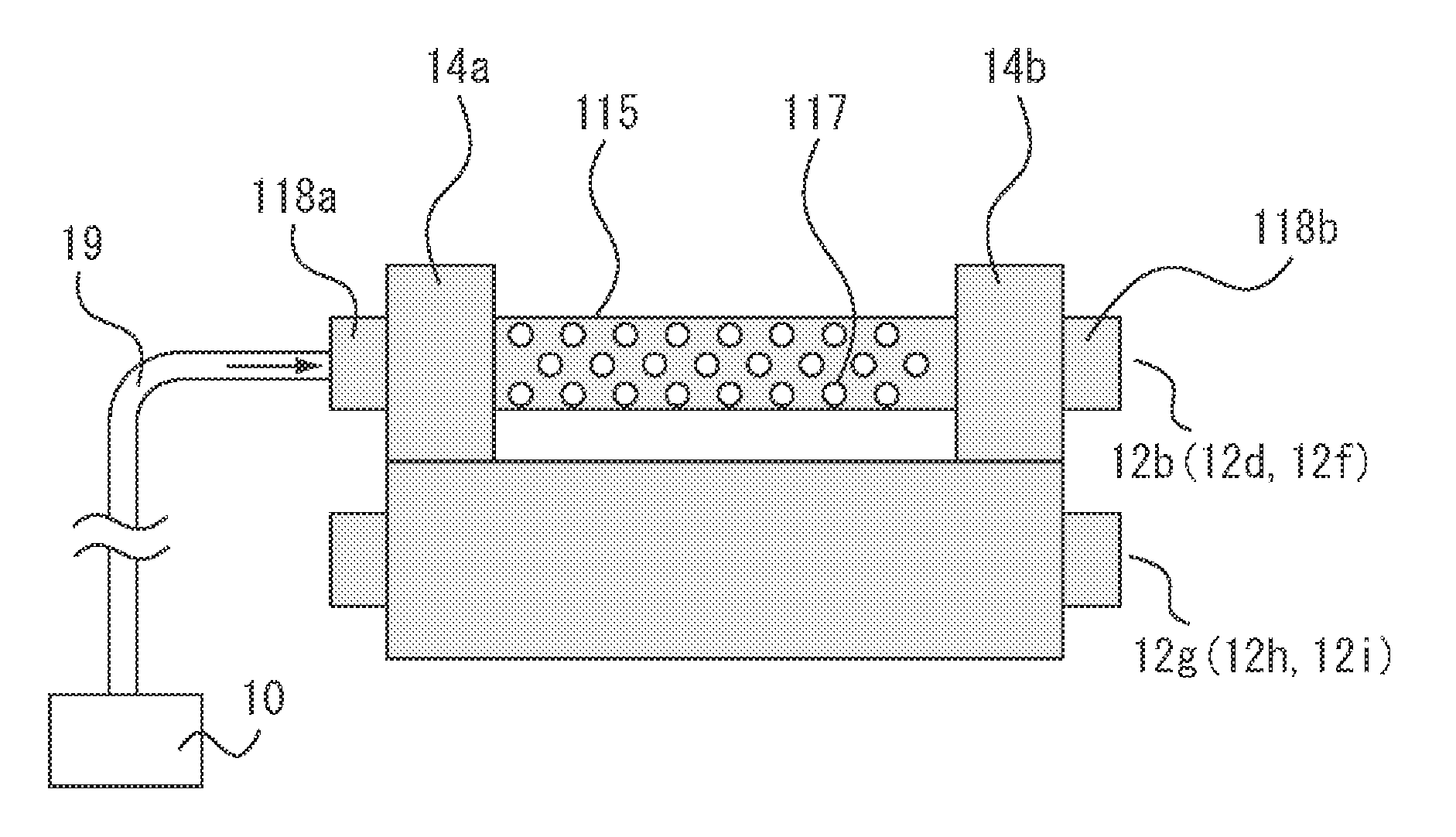
[0018]An image forming apparatus according to a first exemplary embodiment of the present invention conveys a roll-shaped medium, forms an image by supplying ink from an inkjet type recoding head directly to the medium, and dries an ink on the medium by a drier. In the present specification, the “medium” is any sheet-shaped recording medium such as paper, fabric, plastic sheet or film.

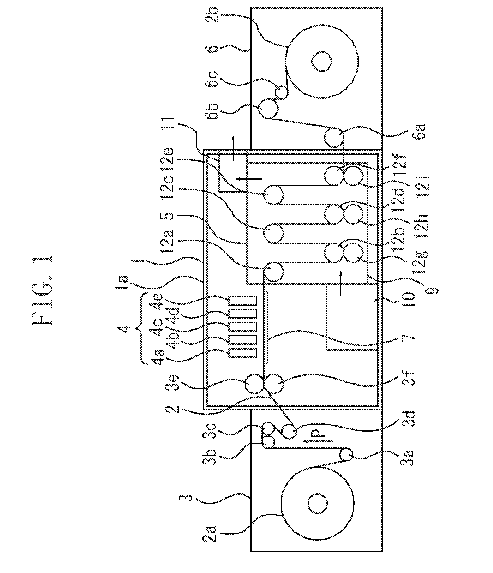
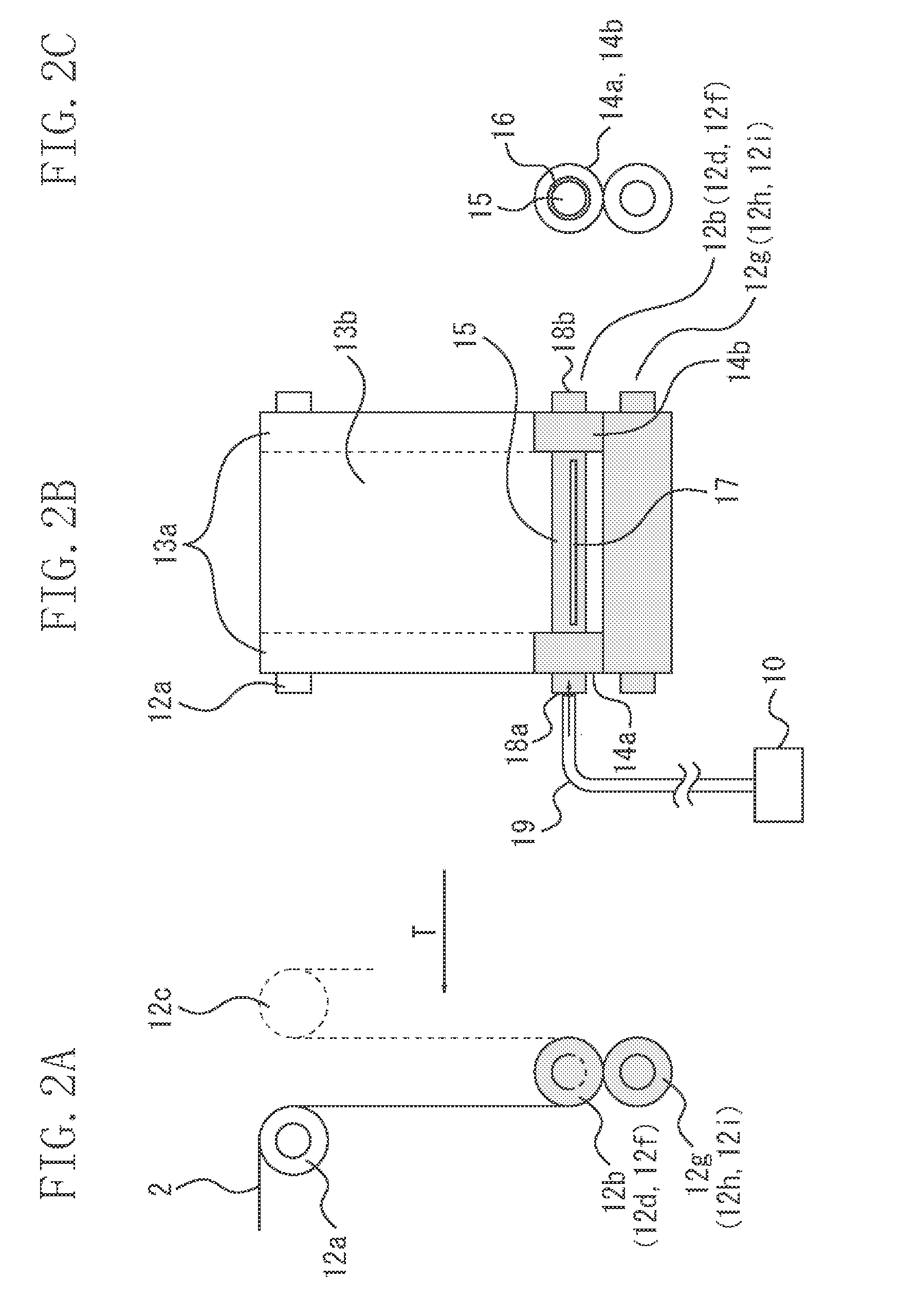
[0019]FIG. 1 illustrates the image forming apparatus according to the first exemplary embodiment of the present invention. In FIG. 1, a roll-shaped medium 2 is wound on a supply roll 2a and a winding roll 2b. The medium 2 has a width of 400 mm, of which 40 mm at each end forms a non-image forming area. The supply roll 2a and the winding roll 2b are rotated in the clockwise direction by a motor. In the present exemplary embodiment, though the medium 2 is a roll she...


PUM


Abstract

An image forming apparatus includes an image forming unit configured to form an image by using liquid, a conveyance mechanism having a roller configured to convey a medium on which the image is formed by the image forming unit or a transfer belt for transferring to a medium an intermediate image formed by the image forming unit, and wherein the roller has a discharge surface on which one or a plurality of holes is formed to blow gas toward the medium or the transfer belt conveyed by the conveyance mechanism.

Description

BACKGROUND OF THE INVENTION[0001]1. Field of the Invention[0002]The present invention relates to an image forming apparatus which forms an image using liquid.[0003]2. Description of the Related Art[0004]In an inkjet type or liquid development type (silver halide photograph type) image forming apparatus, since liquid is applied to a sheet-shaped recording medium (hereinafter simply referred to as “medium”) in the image forming process, there needs to be a drying process for drying such a wet medium. To improve print throughput, the drying process has to be finished for a shorter time. U.S. Pat. No. 5,410,382 discusses a drying apparatus for blowing hot air to a wet medium after the liquid development process to accelerate drying.[0005]The apparatus discussed in the above document achieves effective acceleration of drying by providing a supply chamber with blowout ports for blowing hot air to a surface of the medium from a close position and by positioning each of the blowout ports be...

Claims


Application Information

Patent Timeline
IPC IPC(8): B41J2/01
CPCB41J2/0057B41J13/076B41J11/002B41J11/0022
Inventor MOURI, AKIHIROTANIUCHI, HIROSHI
Owner CANON KK
Why Eureka
Try Eureka