Water level sensor

Inactive Publication Date: 2017-02-23
OKAZAKI MFG
View PDF2 Cites 1 Cited by
  • Summary
  • Abstract
  • Description
  • Claims
  • Application Information

AI Technical Summary

Benefits of technology

The present invention aims to provide a water level sensor with improved accuracy and a suppressed price. The invention uses a platinum resistive element as the heat source of the heat generating body, which allows for a smaller size and lower cost as compared to traditional heat generating wires. The invention also allows for a heat generating body that can provide a sufficient amount of heat in a narrow range, resulting in improved water level detection accuracy without sacrificing price.

Problems solved by technology

Specifically, in the heat generating body using the existing Nichrome wire as the heat source, it is difficult to obtain a sufficient amount of heat generation while having the size of the platinum resistive element.
Even if that amount of heat generation is obtained by densely arranging the heat generating wire using a thin Nichrome wire, fabrication cost is expected to be high.

Method used


Image

  • Water level sensor
  • Water level sensor
  • Water level sensor

Examples


first embodiment

(1) First Embodiment

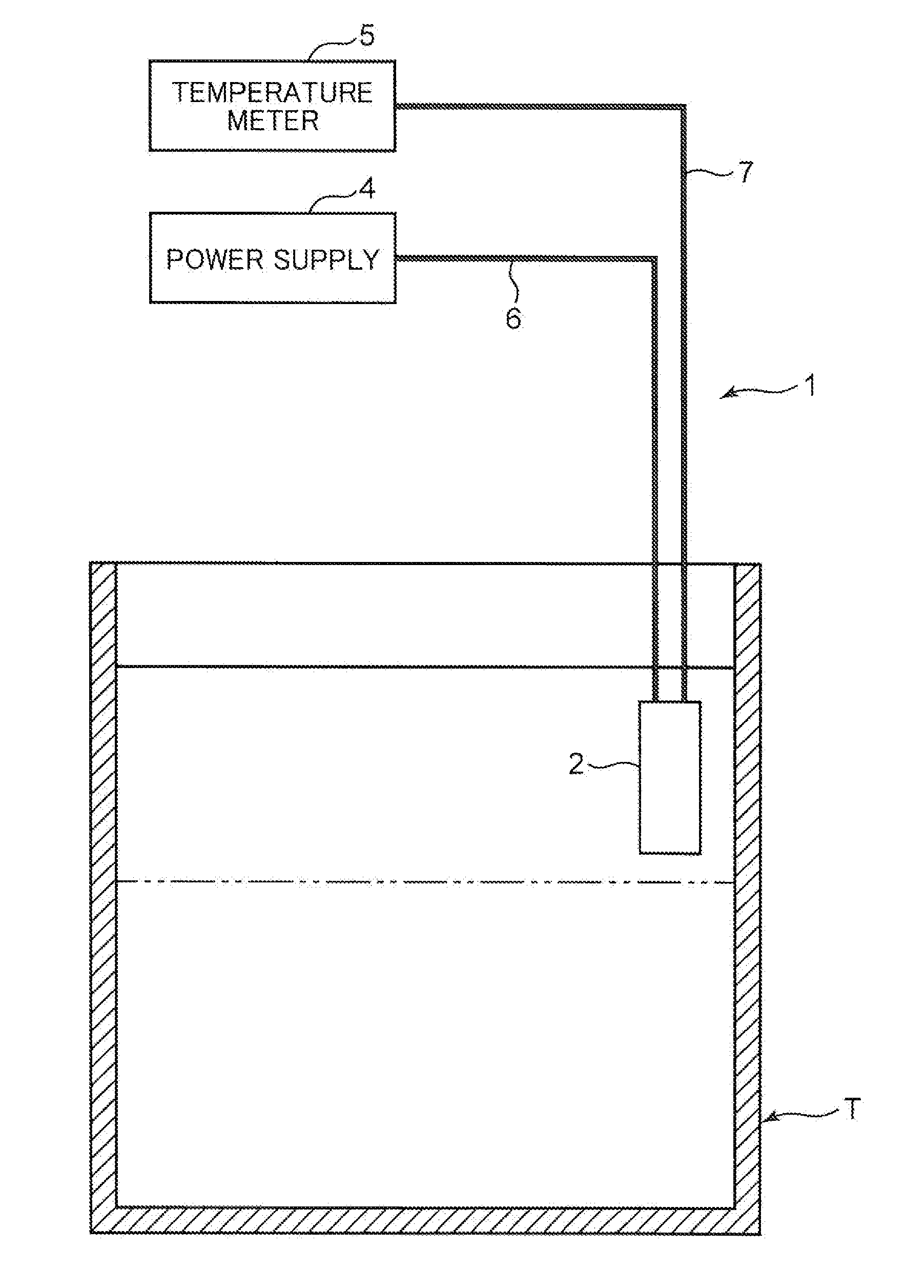
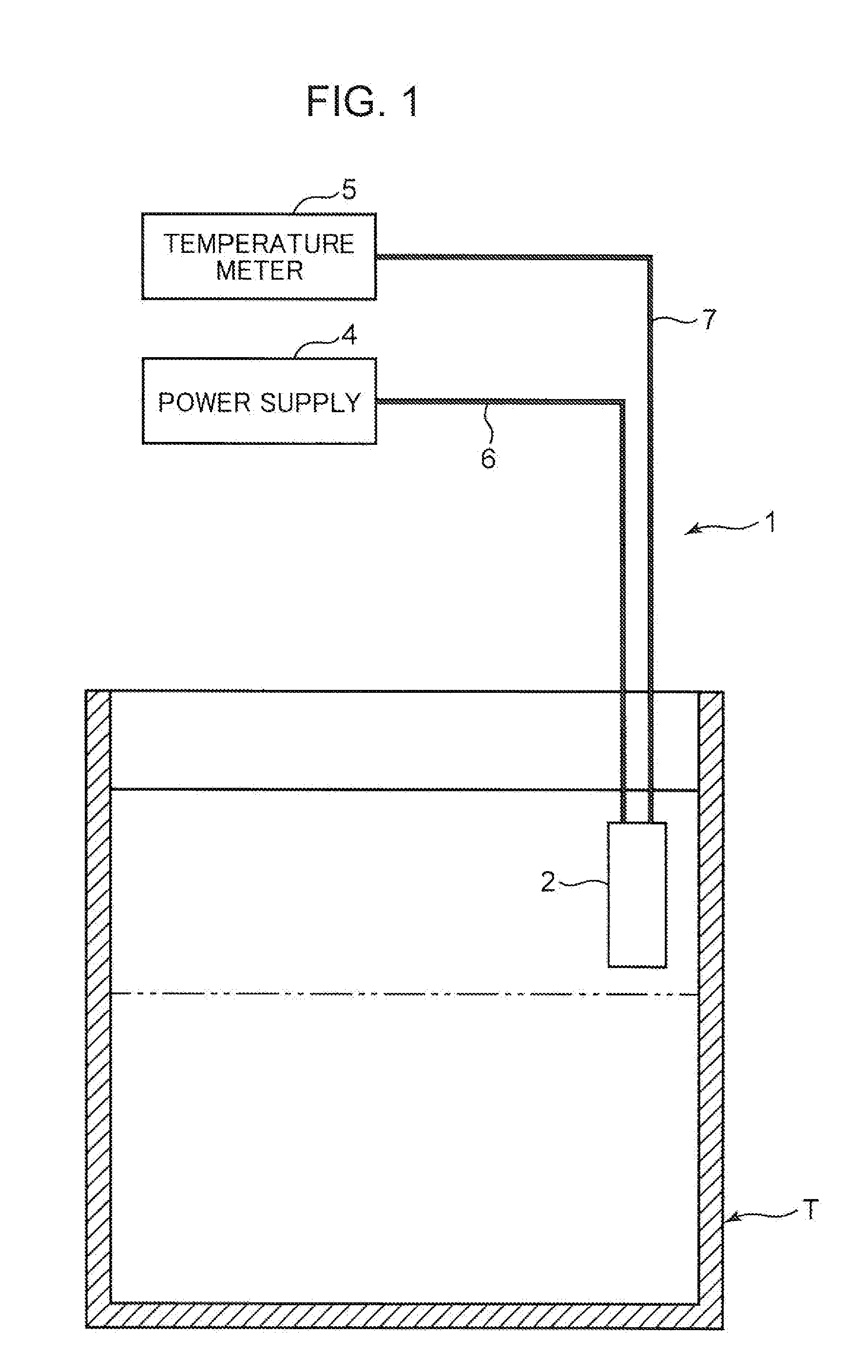
[0019]FIG. I is a conceptual diagram schematically showing a water level detection system using a water level sensor according to one embodiment of the present invention.

[0020]This water level detection system I is for detecting a water level of storage tank (container) T storing water inside. Specifically, the water level detection system 1 includes a water level sensor 2 arranged at a predetermined height of the storage tank T, a power supply 4 for supplying power to this water level sensor 2 and a temperature meter 5 for measuring a temperature based on information from the water level sensor 2 and judging whether the measured temperature is higher or lower than a reference temperature. Whether or not water has reached a height position of the water level sensor 2 is determined based on the above judgment in the temperature meter 5 by electrically connecting cables 6, 7 of the water level sensor 2 respectively to the power supply 4 and the temperature meter 5....

second embodiment

(2) Second Embodiment

[0055]Next, another embodiment of the present invention is described on the basis of FIG. 4. FIG. 4 is a sectional view, corresponding to FIG. 2, showing a water level sensor of this second embodiment.

[0056]A water level sensor 102 of this second embodiment differs from the water level sensor 2 of the first embodiment only in a waterproof coating structure for heat generating lead wires and thermocouple wires. Specifically, waterproof coating is individually applied to the heat generating lead wires 11 and the thermocouple wires 121, 122 by the waterproof coating portions 16, 17 in the water level sensor 2 of the first embodiment. However, the water level sensor 102 of the second embodiment differs in that waterproof coating is collectively applied to heat generating lead wires 111 and thermocouple wires 121, 122.

[0057]Specifically, this water level sensor 102 includes a pair of heat generating lead wires 111 formed of thermocouple wires, which are the same mate...

third embodiment

(3) Third Embodiment

[0060]Next, still another embodiment of the present invention is described on the basis of FIG. 5. FIG. 5 is a sectional view, corresponding to FIG. 2, showing a water level sensor of this third embodiment. FIG. 6 is a sectional view along line VI-VI of FIG. 5.

[0061]A water level sensor 202 of this third embodiment differs from the water level sensor 2 (sic, 102) of the second embodiment in a specific structure of a waterproof coating portion for heat generating lead wires and thermocouple wires. Specifically, waterproof coating is collectively applied to the heat generating lead wires 111 and the thermocouple wires 121, 122 by the waterproof synthetic rein in the water level sensor 102 of the second embodiment. However, the water level sensor 202 of the third embodiment differs in that waterproof coating is applied to heat generating lead wires 111 and thermocouple wires 121, 122 by a metal sheath tube 216 with a sheathing insulating material 217 interposed. Spe...


PUM


Abstract

It is aimed to provide an inexpensive water level sensor capable of improving accuracy. The water level sensor includes a heat generating body 9 operable to generate heat by an electricity, a thermocouple 12 having a temperature measurement point 123 arranged adjacent to the heat generating body 9, a protection tube 13 for housing these heat generating body 9 and thermocouple 12 and an insulating material 14 filled in this protection tube. The heat generating body 9 includes a platinum resistive element 9 as a heat source.

Description

TECHNICAL FIELD[0001]The present invention relates to a water level sensor for detecting a water level of water contained in a container utilizing a heat generating body and a thermocouple.BACKGROUND ART[0002]Conventionally, a water level sensor of this type is widely used as an industrial sensor for detecting water levels of various containers as a water level gauge. For example, a water level sensor shown in patent literature 1 includes, as a water level gauge of a so-called heating thermocouple type, a long and narrow heat generating wire extending in one direction and configured to generate heat by an electricity, a thermocouple having a temperature measurement point arranged adjacent to this heat generating wire, a protection tube configured to house the heat generating wire and the thermocouple and an insulating material filled in this protection tube, and is arranged in the container with its longitudinal direction aligned with a depth direction of the container. Since the am...

Claims


Application Information

Patent Timeline
IPC IPC(8): G01F23/24
CPCG01F23/246
Inventor YAMANA, MASARU
Owner OKAZAKI MFG
Why Eureka
Try Eureka