Touch type electrophoretic display device

Inactive Publication Date: 2010-05-20
LG DISPLAY CO LTD
View PDF2 Cites 26 Cited by
  • Summary
  • Abstract
  • Description
  • Claims
  • Application Information

AI Technical Summary

Benefits of technology

[0017]Therefore, in order to address the above matters, the various features described herein have been conceived. One aspect of the exemplary embodiments

Problems solved by technology

Thus, compared with an electrophoretic display device without a touch function, the touch type electrophoretic display device is disadvantageo

Method used


Image

  • Touch type electrophoretic display device
  • Touch type electrophoretic display device
  • Touch type electrophoretic display device

Examples


Example

[0026]A touch type electrophoretic display device according to an exemplary embodiment of the present invention will now be described in detail with reference to the accompanying drawings.

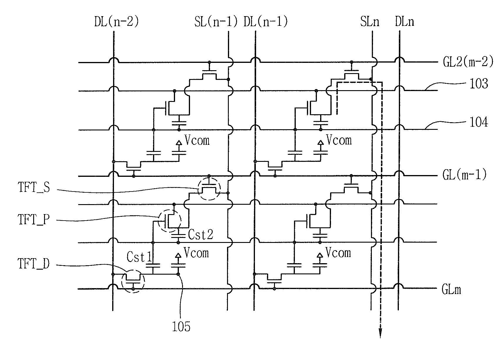
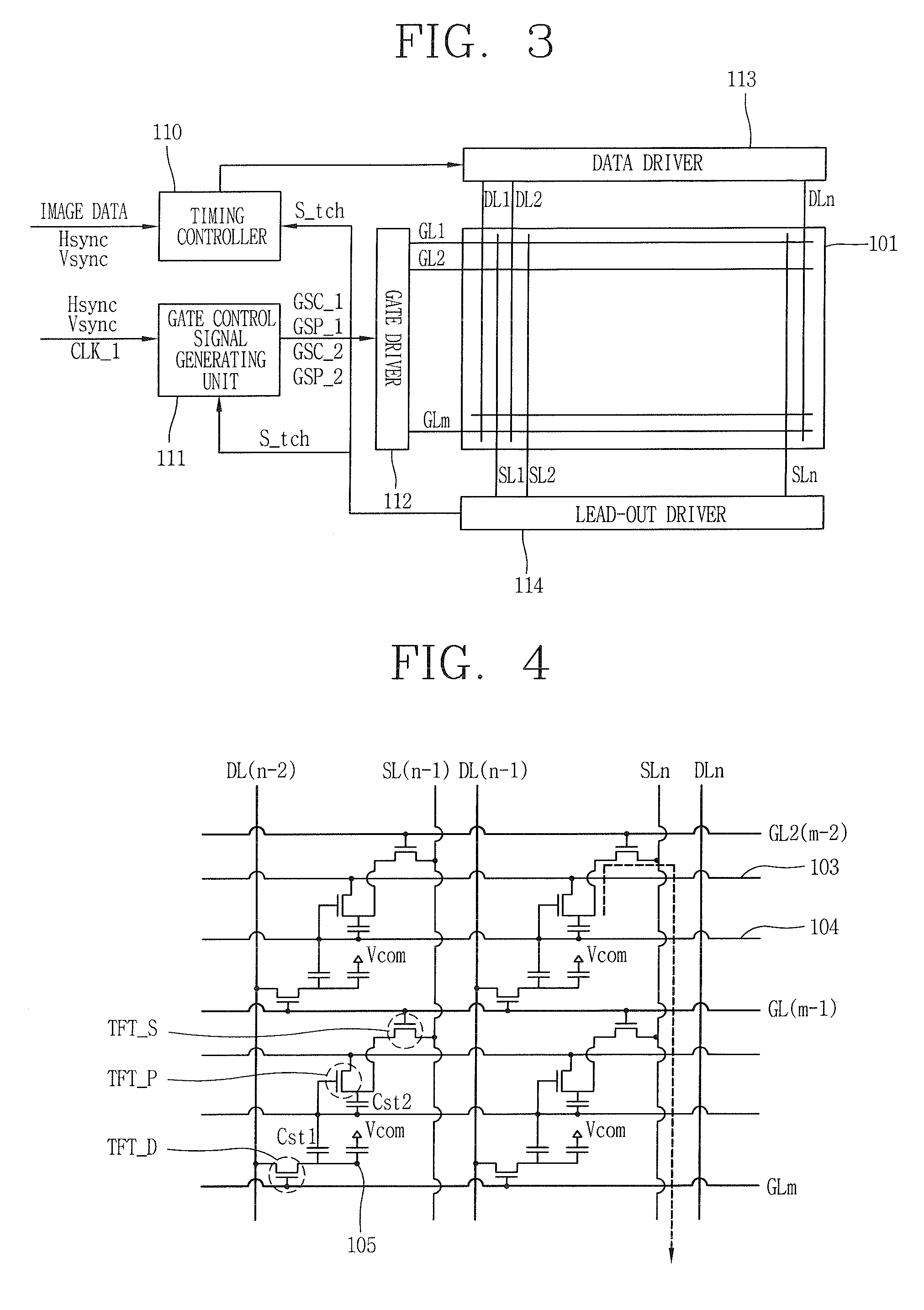
[0027]As shown in FIGS. 3 to 5, a touch type electrophoretic display device according to an embodiment of the present invention includes: a first substrate 101 on which a plurality of gate lines GL1˜GLm and a plurality of data lines DL1˜DLn cross to define a plurality of pixels; a plurality of sensing signal lines SL1˜SLn formed to be parallel to the data lines DL1˜DLn on the first substrate 101; a plurality of first touch driving voltage lines 103 formed to be parallel to the gate lines GL1˜GLm; a driving thin film transistor (TFT_D) formed at each pixel so lo as to be connected to the gate lines GL1˜GLm and the data lines DL1˜DLn; a pixel electrode 105 formed at each pixel so as to be connected to the driving TFT (TFT_D); a switching TFT (TFT_S) formed at each pixel so as to be connected to the s...


PUM


Abstract

A touch type electrophoretic display device includes: a first substrate on which a plurality of gate lines and a plurality of data lines cross to define a plurality of pixels; a plurality of sensing signal lines formed to be parallel to the data lines on the first substrate; a plurality of first touch driving voltage lines formed to be parallel to the gate lines; a driving thin film transistor (TFT) formed at each pixel so as to be connected to the gate lines and the data lines; a pixel electrode formed at each pixel so as to be connected to the driving TFT; a switching TFT formed at each pixel so as to be connected to the sensing signal lines and the gate lines; a lo photo TFT formed in each pixel so as to be connected to the first touch driving voltage lines and the switching TFT and serving to recognize an applied touch; a second substrate attached to the first substrate in a facing manner; a common electrode formed on the second substrate; an electrophoretic film formed between the first and second substrates; a lead-out driver for detecting a position of the photo TFT when a sensing signal is transferred via the switching TFT in a corresponding pixel and the sensing signal lines according to an operation of the photo TFT, and outputting touch data; a gate control signal generating unit for outputting a second gate control signal indicating a touch mode operation when touch data is not inputted from the lead-out driver, and outputting a first gate control signal indicating a driving mode operation for converting an image if it is determined that a touch has been applied upon receiving touch data from the lead-out driver; and a gate driver for driving the gate lines upon receiving the first or second gate control signal from the gate control signal generating unit, wherein a timing at which each gate line is turned on and off when the gate driver receives the first gate control signal and a timing at which each gate line is turned on and off when the second gate control signal is received are different.

Description

BACKGROUND OF THE INVENTION[0001]1. Field of the Invention[0002]The present invention relates to a touch type electrophoretic display device and, more particularly, to a touch type electrophoretic display device capable of minimizing the number or size of gate drivers by minimizing the number of gate lines.[0003]2. Description of the Related Art[0004]In general, an electrophoretic display device is an image displayer using a phenomenon that when a pair of electrodes receiving voltage are put in a colloid solution, colloid particles are moved to one polarity.[0005]The electrophoretic display device is a display device in which a transparent conductive film is coated on a base film which is thin and can be easily bent like paper or plastic to drive electrophoretic suspension and receives much attention as electric paper that may replace the conventional printing mediums such as books, newspapers, and the like.[0006]The electrophoretic display device is advantageous in that it can be e...

Claims


Application Information

Patent Timeline
IPC IPC(8): G09G3/34G06F3/041G06F3/038
CPCG06F3/0412G09G2360/148G09G2300/08G09G3/344G06F3/042
Inventor NAM, SEUNG-SEOK
Owner LG DISPLAY CO LTD
Why Eureka
Try Eureka