Catadioptric Projectors

Active Publication Date: 2010-05-20
SEIKO EPSON CORP
View PDF6 Cites 51 Cited by
  • Summary
  • Abstract
  • Description
  • Claims
  • Application Information

AI Technical Summary

Benefits of technology

[0025]In step 1, above, in a preferred embodiment, creation of the matrix inverse of the light transport matrix includes imposing a Display Constraint upon the light transport matrix, where the Display Constraint specifies that any two distinct light rays emitted from the projector will hit the camera's image sensor at distinct parts, and wherein the imposing of the Display Constraint includes (for each row in light transport matrix T): comparing matrix entries along a common row of the light transport matrix, and nullifying by assigning zero values to all but the highest valued matrix entry in the common row, the resultant matrix being a modified light transport matrix T*. In this approach, the inverse matrix of the modified light transport matrix T* is preferably generated by: identifying in turn each column in the modified light transport matrix as a target column, calculating normalized values for not-nullified entry values in the target column with reference to the target column; creating an intermediate matrix of equal size as the modified light transport matrix; populating each column in the i

Problems solved by technology

Nonetheless, many obstacles still remain to be overcome.
Like pinhole cameras, a projector suffers from limited field-of-view, i.e., it can be difficult to produce a panoram

Method used


Image

  • Catadioptric Projectors
  • Catadioptric Projectors
  • Catadioptric Projectors

Examples


Embodiment Construction

[0051]The recent introduction and rapid adoption of consumer digital projectors has redefined the landscape for displaying images and videos. To model projection geometry, a projector-camera system (i.e. a ProCam system), can be setup and the projector can be treated as a virtual pinhole camera. Classical perspective geometry can then be directly applied to analyze the projection process.

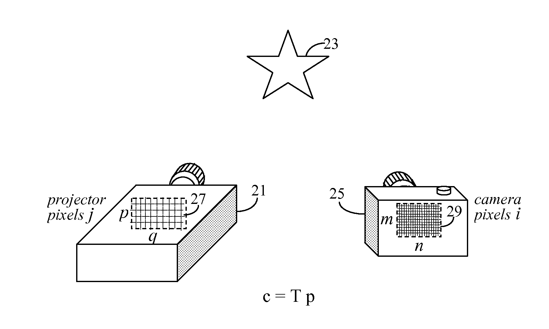
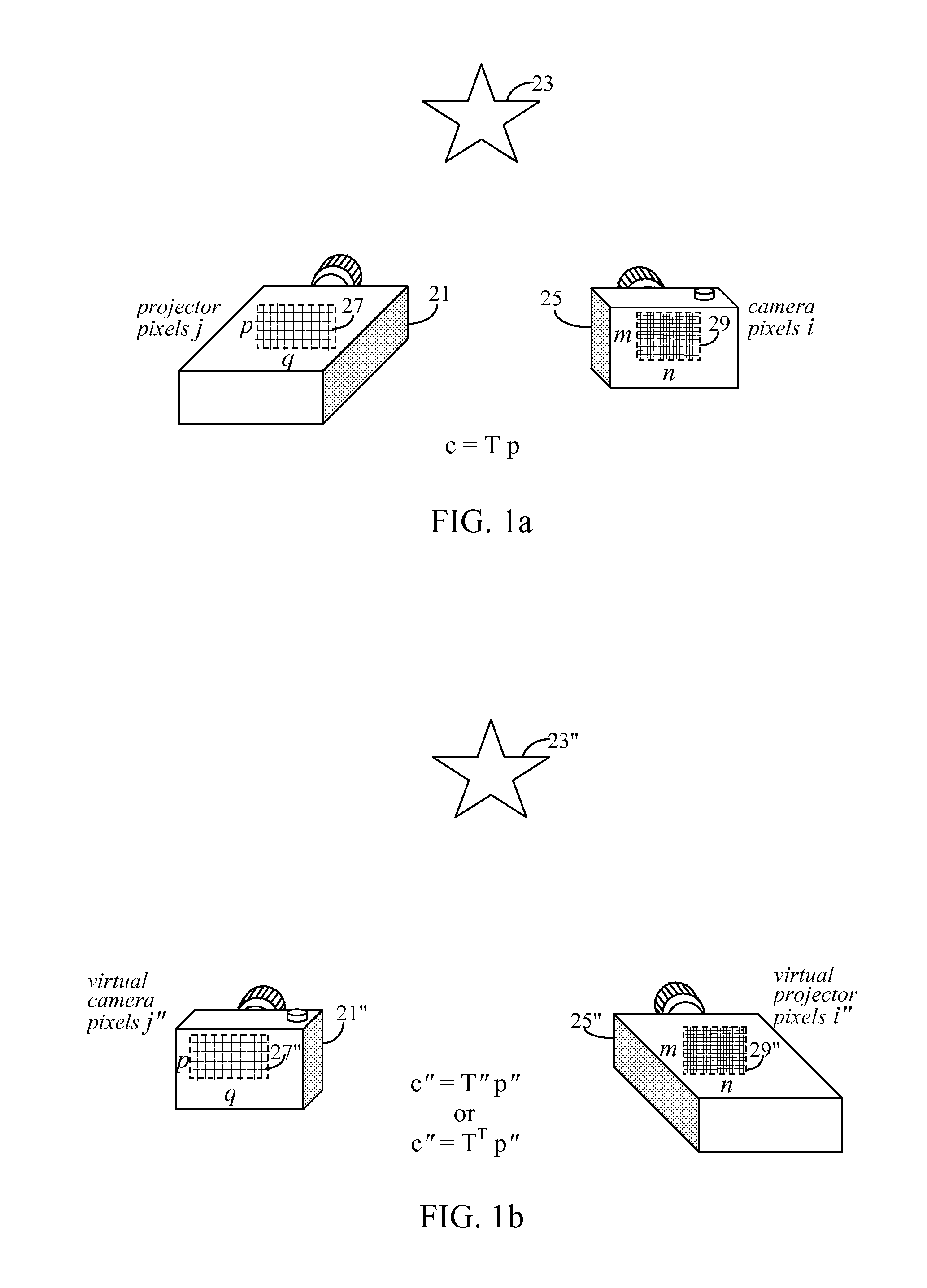
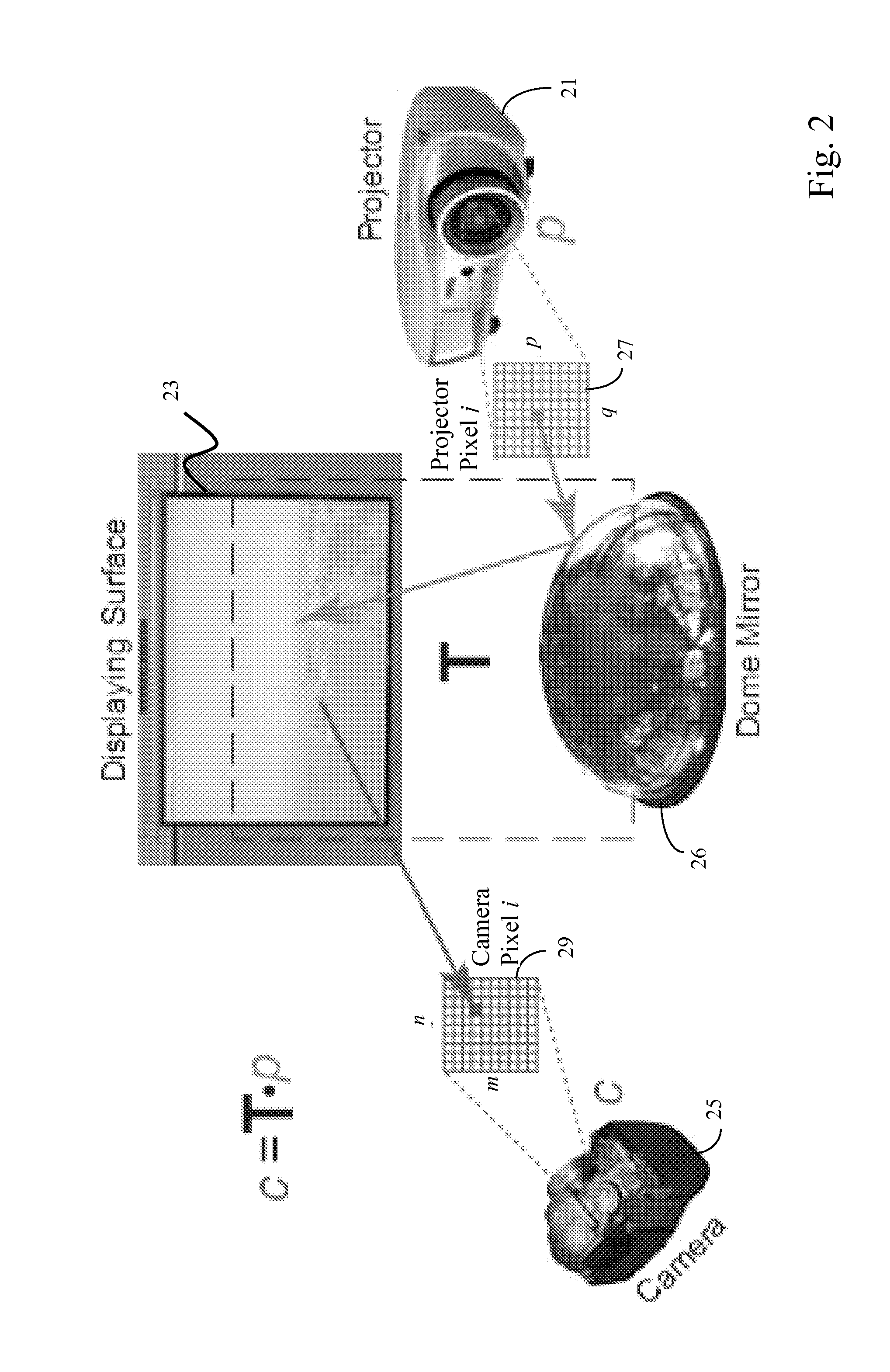
[0052]The basic construct of a projector-camera system can be better understood with reference to FIGS. 1a and 1b. In FIG. 1a, an imaging setup may include a real projector 21 and a real camera 25. Real projector 21 is preferably a digital projector and has an imaging element including an imaging projection array (i.e. projector pixel array 27), consisting of p rows and q columns of individual imaging projection elements (i.e. projector pixels j). Projector pixel array 27 is internal to real projector 21, but for discussion purposes, it is shown as crossed lines within a dotted square on projector 2...


PUM


Abstract

Herein is presented a catadioptric projector by combining a commodity digital projector with additional optical units. By using specially shaped reflectors and/or refractors, a catadioptric projector can offer an unprecedented level of flexibility in aspect ratio, size, and field of view. Also presented, are methods to reduce projection artifacts in catadioptric projectors, such as distortions, scattering, and defocusing. By analysis of projection defocus of reflector and thin refractor based catadioptric projectors, it is shown that defocus blur can be interpreted as spatially-varying Gaussian blurs on an input image. Kernels are measured directly from a light transport matrix, T, and de-convolution is applied to optimize an input image. Practical uses of catadioptric projectors in panoramic and omni-directional projections are also demonstrated.

Description

CROSS-REFERENCE TO RELATED APPLICATIONS[0001]This application claims the benefit of U.S. Provisional Application No. 61 / 116,152 filed Nov. 19, 2008 under 35 U.S.C. §119(e) and is hereby incorporated by reference in its entirety.BACKGROUND[0002]1. Field of Invention[0003]The present invention is directed towards methods of creating and optimizing images in a catadioptric projector system. More specifically, the present invention presents methods of addressing defocus and distortion issues in projected images, and particularly in images projected using reflector and / or refractor materials.[0004]2. Description of Related Art[0005]High resolution and high contrast projectors are increasingly used in a wide array of commercial and scientific applications, ranging from shape acquisition, to virtual environments and Imax© theaters. In vision and graphics applications, cameras are often combined with projectors to form a projector-camera, or ProCam, system, for creating so-called “intellige...

Claims


Application Information

Patent Timeline
IPC IPC(8): H04N17/00
CPCH04N17/04H04N9/3191
Inventor DING, YUANYUANXIAO, JING
Owner SEIKO EPSON CORP
Why Eureka
Try Eureka