

Keyboard, Lighting Module for Keyboard and Electronic Apparatus
a technology for electronic devices and lighting modules, applied in the direction of electric devices, instruments, casings/cabinets/drawers, etc., can solve the problems of increasing the number of parts forming a keyboard, the operator is hard to recognize the keytop that should be operated, and the keyboard is difficult to opera
- Summary
- Abstract
- Description
- Claims
- Application Information
AI Technical Summary
Problems solved by technology
Method used
Image

Examples
first embodiment
[0025]Hereinafter, the invention will be described with reference to FIGS. 1 to 6.
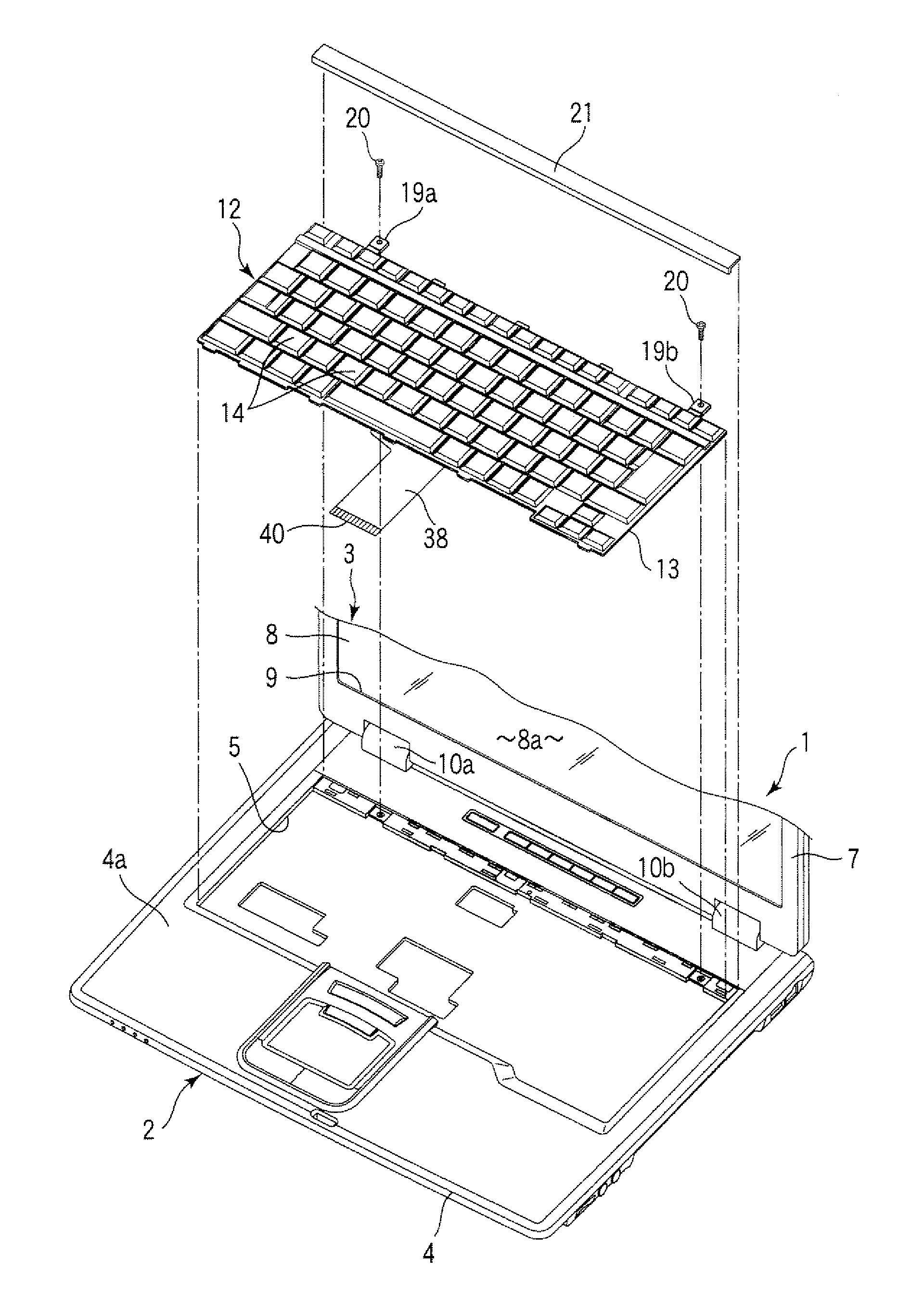
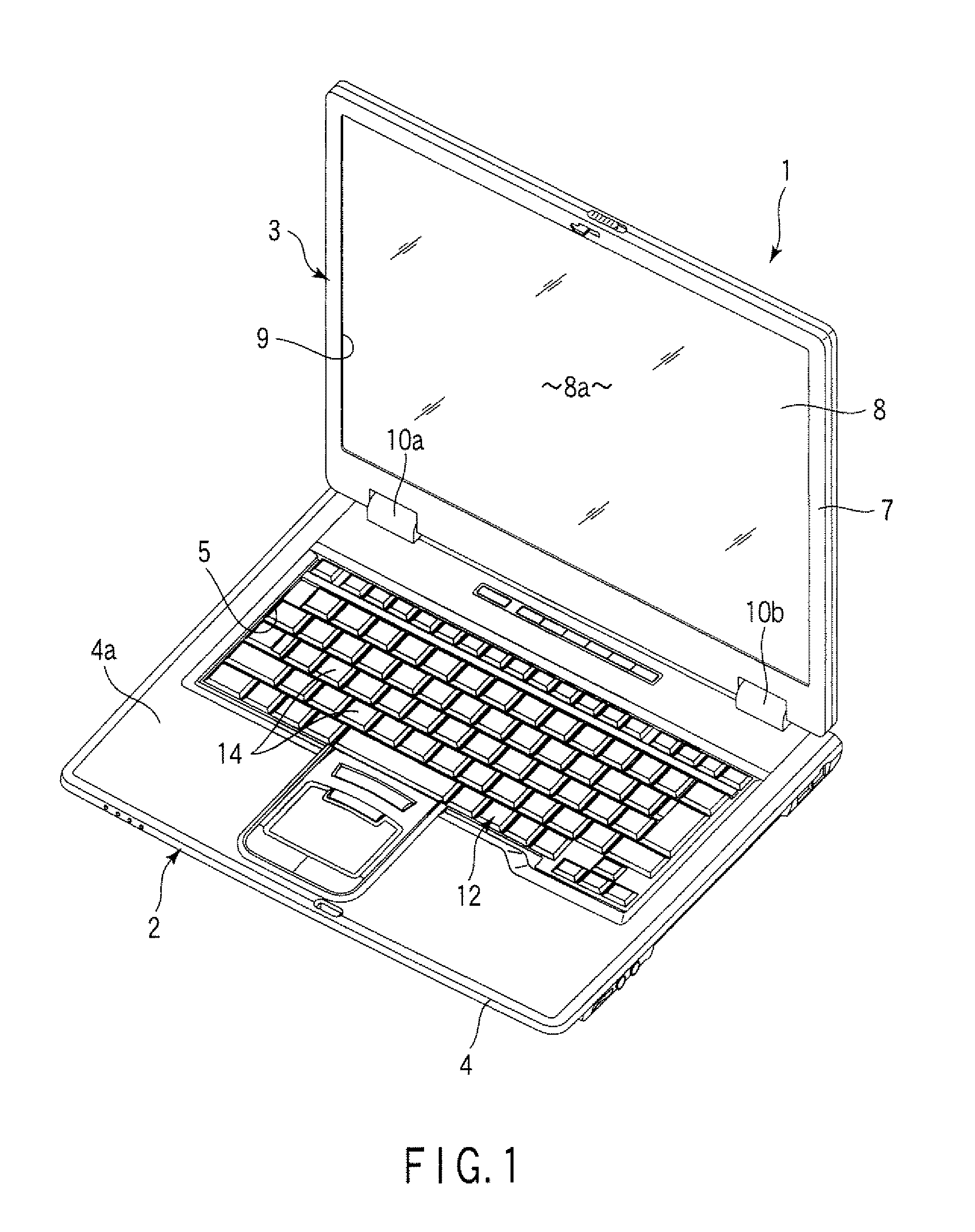
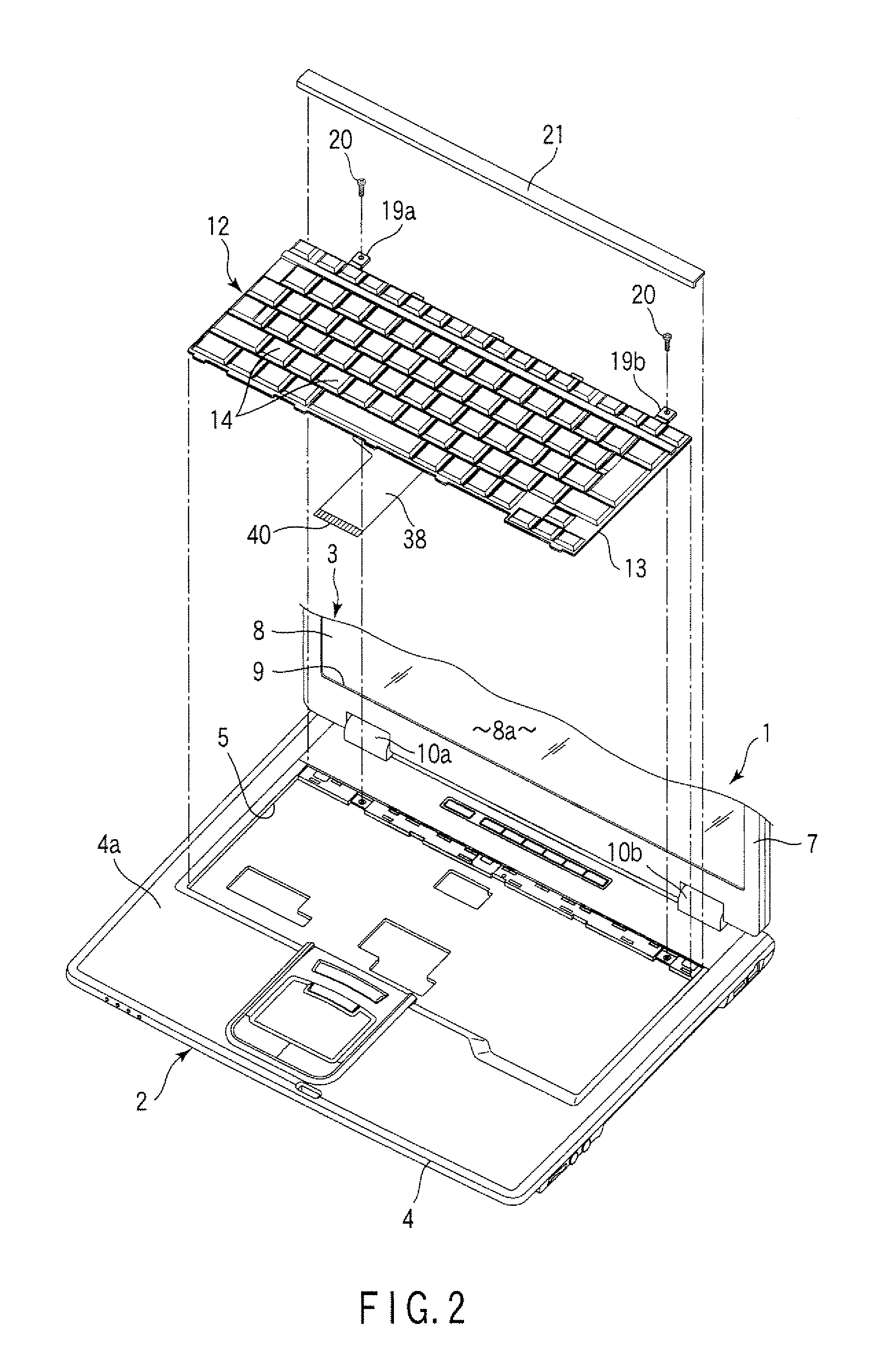
[0026]FIGS. 1 and 2 disclose a portable computer 1, which is an example of an electronic apparatus. The portable computer 1 comprises a computer main module 2 and a display module 3.
[0027]The computer main module 2 has a flat box-shaped housing 4. The housing 4 contains main structural elements such as a print circuit board on which a CPU is mounted and a hard disk drive, for example. The housing 4 has a flat upper surface 4a. A keyboard mount area 5 is formed in a central part of the upper surface 4a of the housing 4.
[0028]The display module 3 includes a flat box-shaped display housing 7 and a liquid crystal display panel 8 contained in the display housing 7. The liquid crystal display panel 8 has a screen 8a. The screen 8a is exposed outside the display module 3 from an opening 9 which is made the front surface of the display housing 7.
[0029]The display module 3 is supported by a pair of hinge parts ...
second embodiment
[0077]For example, FIG. 7 discloses the invention.
[0078]The second embodiment differs from the first embodiment in that the entire surface of the press surface 14a of the keytop 14 glows. The other configurations of the keyboard 12 are same as those of the first embodiment. Accordingly, in the second embodiment, structural elements same as those of the first embodiment will be referred to by the same reference signs, and descriptions of such elements will be omitted.
[0079]As shown in FIG. 7, the press surface 14a of the keytop 14 having optical transparency is exposed outside the keyboard 12 without being covered with a film having a light blocking effect. A letter or a symbol indicating the kind and the function of the keytop 14 is formed on the press surface 14a of the keytop 14 by means of printing, for example.
[0080]When light emitted from the light-emitting diode 15 is led to the back surface of the keytop 14, the light penetrates the keytop 14 and reaches the press surface 14a...
third embodiment
[0081]FIG. 8 discloses the invention.
[0082]The third embodiment differs from the first embodiment in positional relationship between the membrane switch 15 and the lightguide plate 52. The other configurations of the keyboard 12 are same as those of the first embodiment. Therefore, in the third embodiment, the structural elements same as those of the first embodiment will be referred to by the same reference signs, and descriptions of such elements will be omitted.
[0083]As shown in FIG. 8, a membrane sheet 29 of the membrane switch 15 is stacked on a substrate 13 of the keyboard 12. A light-emitting diode 51 as a light source is mounted on the upper surface of a second sheet 31 of the membrane sheet 29. According to the embodiment, the light-emitting diodes 51 are arranged at intervals in the width direction of the membrane switch 15 in the front-end part of the upper surface of the second sheet 31.
[0084]The main body 58 of the lightguide plate 52 is stacked on the upper surface of ...
PUM
 Abstract
Description
Claims
Application Information