
Ladder

Inactive Publication Date: 2010-06-03
TIANJIN KELIN MOLD MFG TECH
View PDF13 Cites 10 Cited by
  • Summary
  • Abstract
  • Description
  • Claims
  • Application Information

AI Technical Summary

Benefits of technology

[0029]1) since a key is required to extend the ladder, a problem that incorrect operation may hurt operators is solved, and thus safety is greatly improved.
[0030]2) retraction of the ladder is very convenient, the operator only need to use one hand to turn the key, and another hand to retract the ladder section, and therefore the ladder of the invention can be operated by one operator only.
[0031]3) the ladder features improved functionality: as the ladder is extended, different kinds of ladder: such as an extension ladder, a combined extension ladder and a step ladder that fit for different climbing operations can be formed. A height of the ladder ranges from 1 to 7 m. As the invention is used as a step ladder, a height thereof can be adjusted in a range between 1 and 7 m, and a length of the platform can be adjusted in a range of 0.8 and 2.2 m.
[0032]4) the invention occupies small space during transportation or retraction, and can be received by two normal-sized suitcases after being retracted.

Problems solved by technology

However, there are several problems with them: firstly, they have complex structure, single functions, and poor extension performance; secondly, they are difficult to be combined; finally, they lack safety and incorrect operation thereof often hurt operators.

Method used


Image

  • Ladder
  • Ladder
  • Ladder

Examples


Embodiment Construction

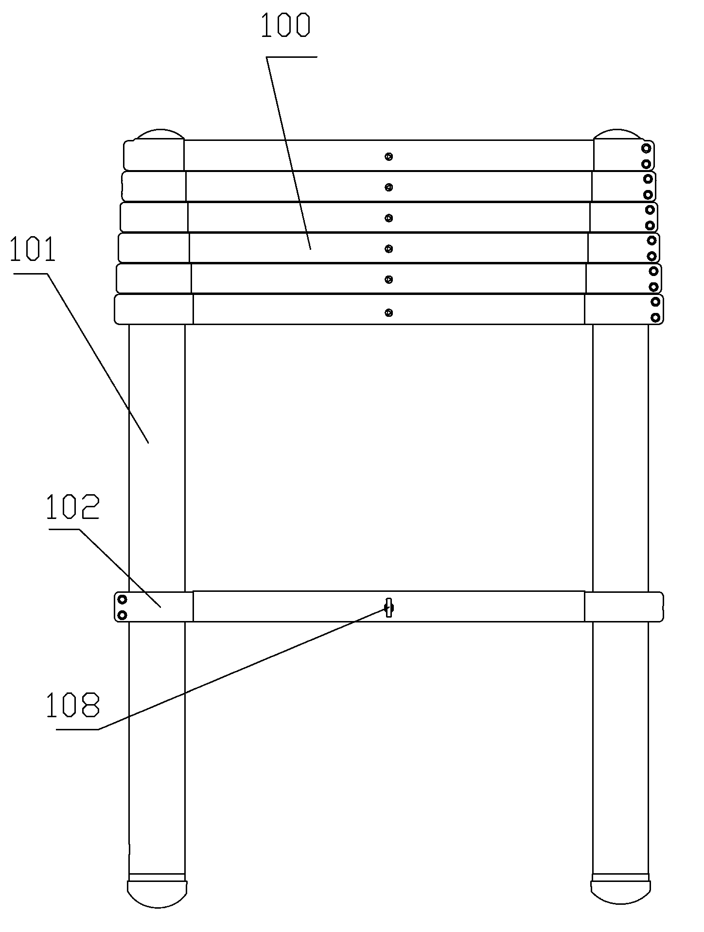
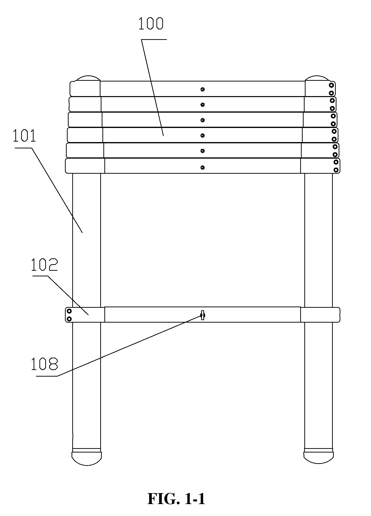
[0050]As shown in FIG. 1-1, an extension ladder 100 of the invention comprises multiple ladder sections. The ladder section comprises a pair of pin holes 103, a pair of columns 101, and a rung 102. The columns 101 of adjacent ladder sections are fit with each other, and diameters of the columns 101 of the ladder sections increase from the top to the bottom. The pin holes 103 are disposed on the columns 101.

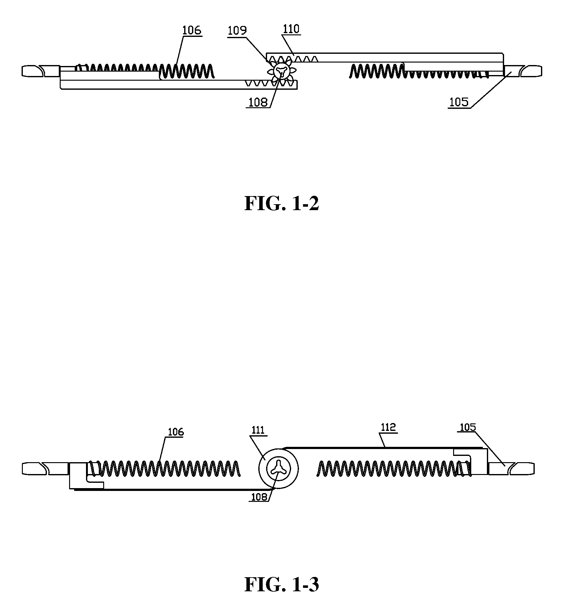
[0051]As shown in FIG. 1-2, the rung 102 of an embodiment of the invention comprises a pair of pins 105, a pair of springs 106, a gear 109, a pair of gear racks 110, and a pair of mounting rings. The pin holes 103 operate to receive the pins 105, and the pins 105 are coaxial.

[0052]The gear 109 is disposed on a side wall of the rung 102 and engaged with the gear rack 110.

[0053]One end surface 107 of the gear 109 sticks out from the side wall of the rung 102, and a key hole 108 is disposed on the end surface 107 of the gear 109.

[0054]The mounting ring operates to fix the pin 105.

[00...


PUM


Abstract

An extension ladder, including multiple ladder sections, each including a pair of pin holes, a pair of columns, and a rung, including a pair of pins, a pair of springs, a gear, a pair of gear racks, and a pair of mounting rings, wherein the columns of adjacent ladder sections are fit with each other, diameters of the columns of the ladder sections increase from the top to the bottom, the pin holes are disposed on the columns, and operate to receive the pins, the pins are coaxial, the gear is disposed on a side wall of the rung and engaged with the gear rack, one end surface of the gear sticks out from the side wall of the rung, a key hole is disposed on the end surface of the gear, the mounting ring operates to fix the pin, and the spring is contacted with the pin.

Description

CROSS-REFERENCE TO RELATED APPLICATIONS[0001]This application is a continuation of International Patent Application No. PCT / CN2007 / 070226 with an international filing date of Jul. 3, 2007, designating the United States, now pending, and further claims priority benefits to Chinese Patent Application No. 200710057415.2 filed on May 22, 2007. The contents of all of the aforementioned applications, including any intervening amendments thereto, are incorporated herein by referenceBACKGROUND OF THE INVENTION[0002]1. Field of the Invention[0003]The invention relates to a ladder, a combined ladder and a step ladder, and more particularly to an extension ladder, a combined extension ladder and a step ladder.[0004]2. Description of the Related Art[0005]Extension ladders, combined extension ladders and step ladders are widely used nowadays. However, there are several problems with them: firstly, they have complex structure, single functions, and poor extension performance; secondly, they are d...

Claims


Application Information

Patent Timeline
IPC IPC(8): E06C1/02E06C1/30E06C7/02E06C7/08E06C7/50
CPCE06C1/125E06C7/42E06C1/39E06C1/32
Inventor WANG, KECHENG
Owner TIANJIN KELIN MOLD MFG TECH
Learn More