Drip tray

Inactive Publication Date: 2010-06-03
FOX KEVIN
View PDF3 Cites 5 Cited by
  • Summary
  • Abstract
  • Description
  • Claims
  • Application Information

AI Technical Summary

Benefits of technology

[0015]The transparent window and frame may be formed in one piece, e.g. the cover may be an integrally formed element. Alternatively, a transparent pane of material (e.g. plastic or glass) may be sealed within an aperture defined by a frame. The transparent window and frame may lie on the same plane. Alternatively, the transparent window may be raised above the frame. This arrangement can promote draining and preventing pooling of liquid on the outer surface.
[0016]The display indicia may have any form suitable for retention in the compartment. For example, it may be a sheet-like member and the compartment may include a slot or projecting fla

Problems solved by technology

Such pockets are prone to retain spilled liquid and/or can be d

Method used


Image

  • Drip tray
  • Drip tray
  • Drip tray

Examples


first embodiment

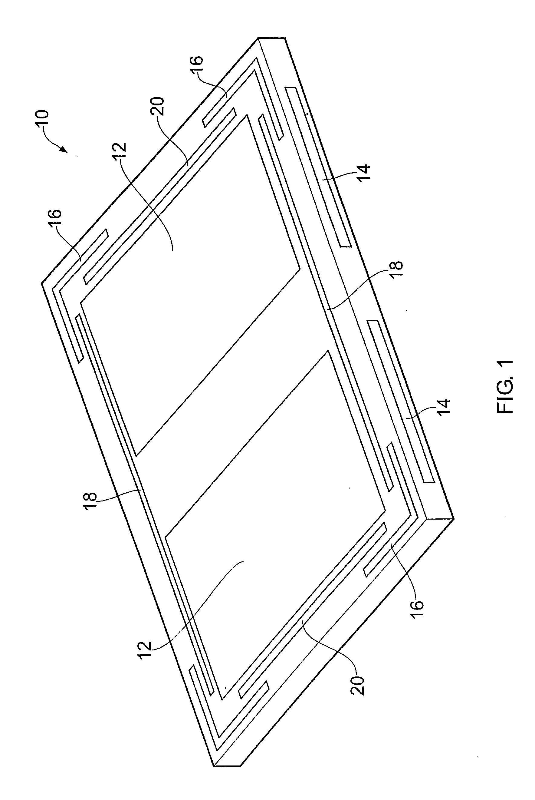
[0036]FIG. 1 shows an advertising insert 10 for a drip tray that is the invention. The insert is made from a rectangular piece of rigid material, e.g. plastic. The insert can be formed from a single piece of material. The outer surface of the insert 10 (shown facing upwards in FIG. 1) has two transparent windows 12 which permit the interior of compartments formed within the insert 10 to be seen. The compartments are rectangular and correspond to the area covered by the respective windows 12. Each compartment can receive an advertisement through an entry slot 14 formed in one side of the insert 10. The insert 10 shown in FIG. 1 is reversible (i.e. the under surface is identical to the outer surface). Thus, two further transparent windows are formed on the surface opposite the outer surface shown in FIG. 1. A double-sided advert can therefore be inserted into each compartment allowing the insert 10 to display four adverts in total. The adverts may be targeted for different times of da...

second embodiment

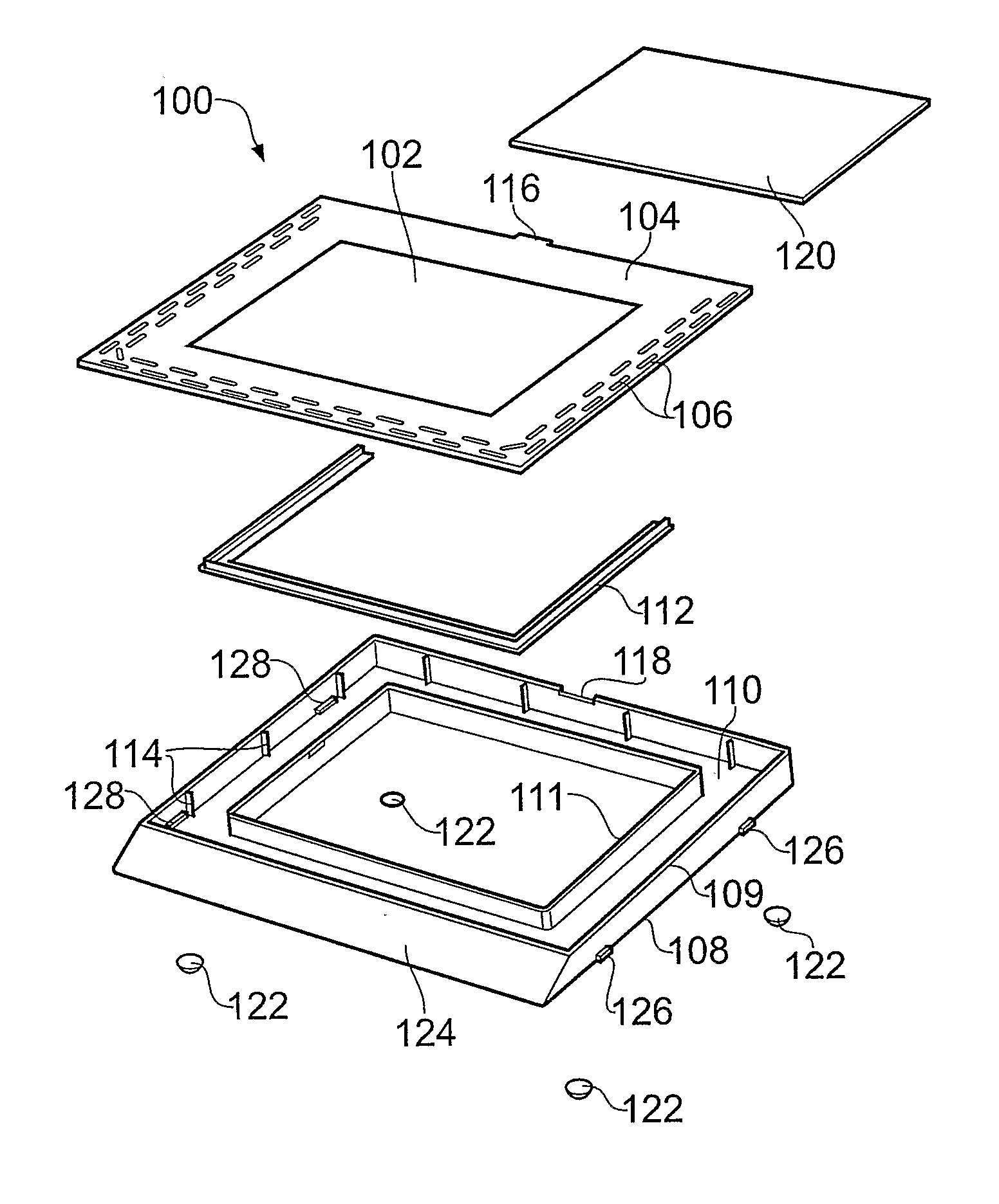
[0045]FIG. 6 shows a perspective view of a drip tray 40 that is the invention. The components of the drip tray 40 are exploded to aid understanding. The drip tray 40 has an outer surface (facing upwards in FIG. 6) formed by a transparent window pane 42 which is mounted within a frame 44. The join between the window pane 42 and frame 44 is sealed to prevent liquid from passing therethrough. Drainage passages 46 are formed along a bottom edge of the frame 44. The drainage passages 46 pass all the way through the frame 44. The window pane 42 and frame 44 form a cover, which is mounted on a base 48. In the embodiment shown in FIG. 6, the cover is welded to the base, i.e. the frame 44 is welded to the base 48. The base 48 has a rectangular channel 50 shaped to match (e.g. underlie) the frame 44. Thus, in this embodiment, an inner upstanding wall 51 of the channel 50 is welded to an inner edge of the frame 44 and an outer upstanding wall 49 of the channel 50 is welded to an outer edge of ...

third embodiment

[0055]FIG. 11 shows a side view of the drip tray 70 in use. It is tilted by having a pair of back feet 80 projecting further from the bottom of base 78 than a pair of front feet 81. This tilting provides a flow direction for liquid spilled on the outer surface of the drip tray 70; liquid flows down towards the bottom edge of the drip tray 70. The arrangement of the drainage inlets 76 in the third embodiment is selected based on the tilting of the outer surface: all of the drainage inlets 76 are provided downstream of the top edge of the drip tray 70. The drainage inlets 76 are provided in an overlapping formation in which there is no straight line downstream flow path for liquid from the transparent window pane 74 to the outer edge of the frame 72 whilst enabling the frame to possess a sufficient level of structural strength.

[0056]The underside of the drip tray 70 is shown in FIG. 12. In this embodiment sheet-like display indicia can be retained in the compartment 82 by being slid i...


PUM


Abstract

A drip tray (40) having an outer surface which comprises a transparent window pane (42) surrounded by a frame (44) is disclosed. The transparent window pane (42) lies over a compartment (60) adapted to retain display indicia (54), e.g. advertising material. An enclosed volume (50) lies under the frame (44) and is in fluid communication with the outer surface via drainage passageways (46). The compartment (60) is isolated from the outer surface and the enclosed volume so that liquid spilled on the outer surface does not contaminate the display indicia (54).

Description

TECHNICAL FIELD[0001]This invention relates to a drip tray, e.g. suitable for catching liquid spilled from drinks served at a bar. In particular it relates to a drip tray adapted to display indicia, e.g. advertising material.BACKGROUND TO THE INVENTION[0002]To protect the surface of a bar at service points, it is common to have some means of absorbing or catching liquid that can be spilled at the point of sale. Examples include absorbent mats, e.g. beer towels, and drip trays.[0003]Typically drip trays comprise a liquid-retaining tray having a perforated serving surface positioned thereover. Liquid spilled on the serving surface drains through perforations into the tray.[0004]As drip trays are to be found at the point of sale, they are ideal objects for displaying marketing material. It is known to apply indicia, e.g. brand logos, to drip trays. However, it is desirable to be able to vary the material that is displayed, so drip trays with pockets for holding replaceable indicia have...

Claims


Application Information

Patent Timeline
IPC IPC(8): B65D85/00B65D1/34
CPCG09F23/06A47G23/0306
Inventor FOX, KEVIN
Owner FOX KEVIN
Why Eureka
Try Eureka