

Holder and wringer for a sponge
- Summary
- Abstract
- Description
- Claims
- Application Information
AI Technical Summary
Benefits of technology
Problems solved by technology
Method used
Image

Examples
Embodiment Construction
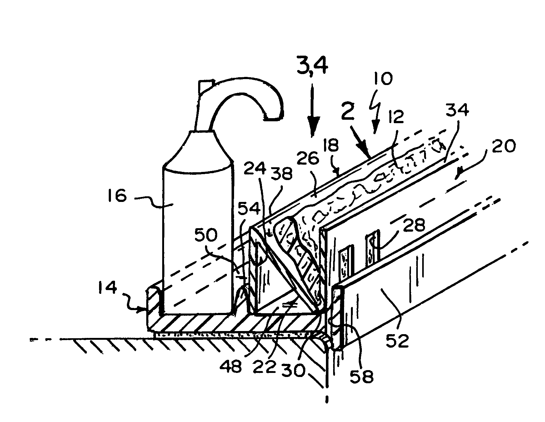
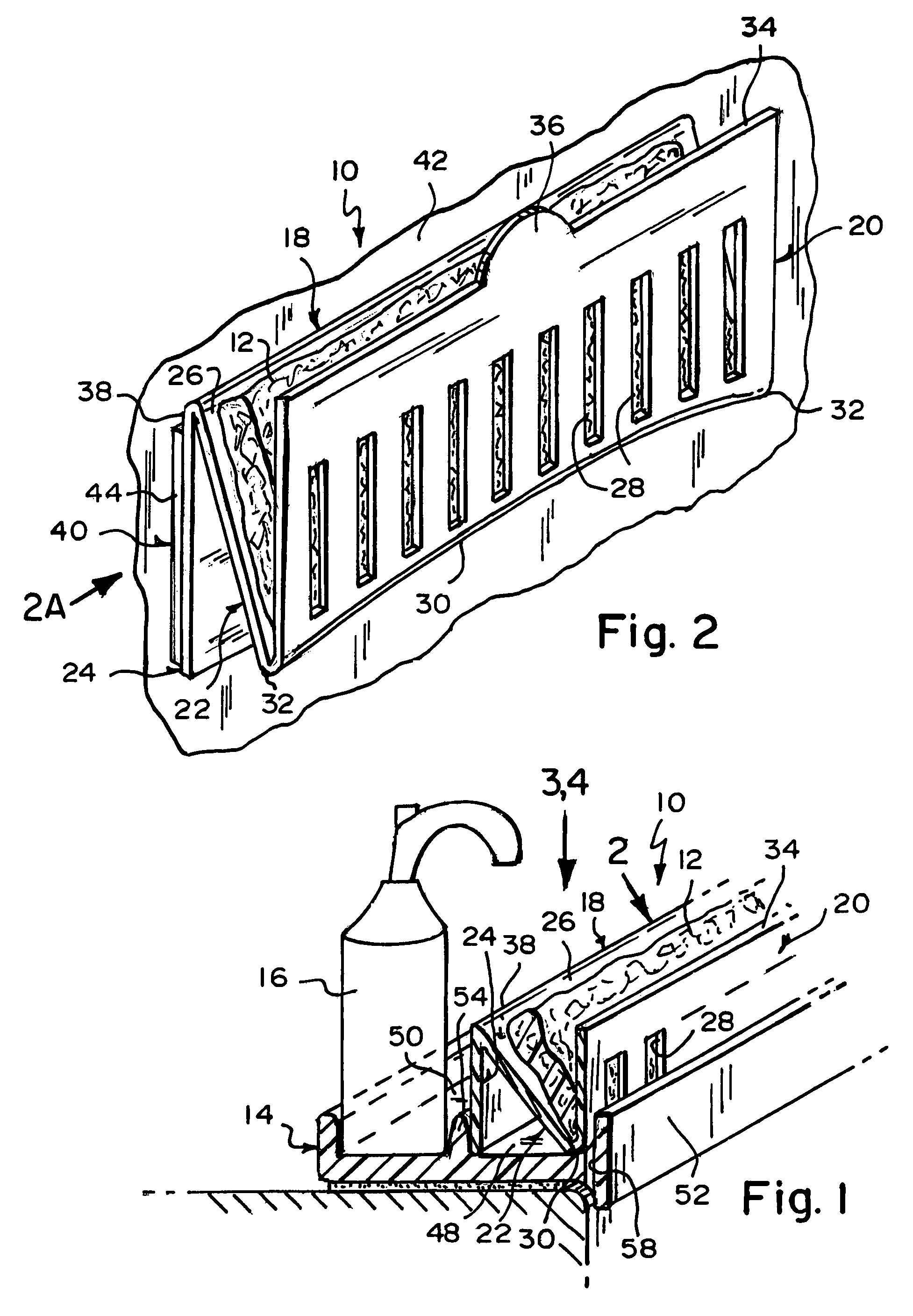
[0026]Referring now to the figures, in which like numerals indicate like parts, and particularly to figure, the holder and wringer of the present invention is shown generally at 10 for a sponge 12 and resting in a soap dish 14 having a liquid soap dispenser 16 thereon.
[0027]The configuration of the holder and wringer 10 can best be seen in FIGS. 1 and 2, and as such, will be discussed with reference thereto.
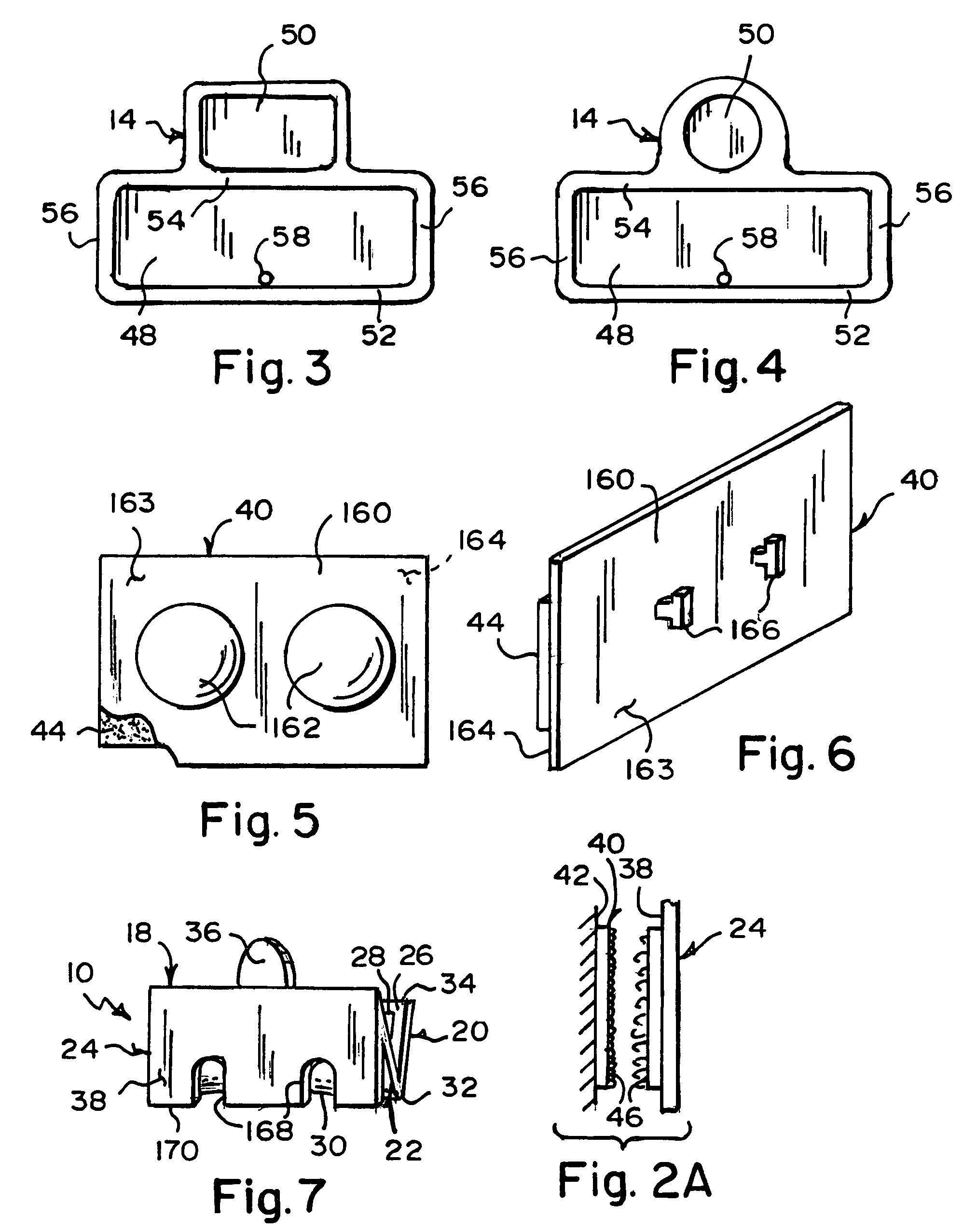
[0028]The holder and wringer 10 comprises a sheet of material 18. The sheet of material 18 is so configured for resting in the soap dish 14, for holding the sponge 12, and for allowing wringing of the sponge 12 once removed from the soap dish 14.
[0029]The sheet of material 18 is microwavable so as to allow sanitizing thereof.
[0030]The sheet of material 18 is a springy material, such as, but not limited to, flexible plastic, so as to allow squeezing thereof for wringing out the sponge 12 held therein.
[0031]The sheet of material 18 is bent so as to have an N-shaped lateral cross se...
PUM
 Abstract
Description
Claims
Application Information