Ankle brace

Active Publication Date: 2005-04-05
BAUERFEIND GMBH & CO
View PDF20 Cites 11 Cited by
  • Summary
  • Abstract
  • Description
  • Claims
  • Application Information

AI Technical Summary

Benefits of technology

With this design of the connections, there are in effect in the region of the ankle bone two subchambers situated next to the ankle bone and three juxtaposed subchambers in the further region of the arms of the brace in the transition of the lines towards the knee, said subchambers all being part of the single cushioning chamber of each arm of the brace and therefore being inflated when the cushioning chamber is inflated and also being able to equalize each other with regard to their internal pressure towards the entire region of the cushioning chamber. This design results, next to the ankle bone, in a region with two larger subchambers and, in the region at the end of the “V” formed by the connections, in three juxtaposed subchambers the cross section of which in the inflated state is smaller than the cross section of the two subchambers in the region of the ankle bone. When, therefore, during walking, a pumping effect is exerted on the two subchambers in the region of the ankle bone, this effect gives rise to a pressure in the dir

Problems solved by technology

According to the information in the patent specification, however, the use of only

Method used


Image

  • Ankle brace
  • Ankle brace
  • Ankle brace

Examples


Example

DETAILED DESCRIPTION OF THE DRAWINGS

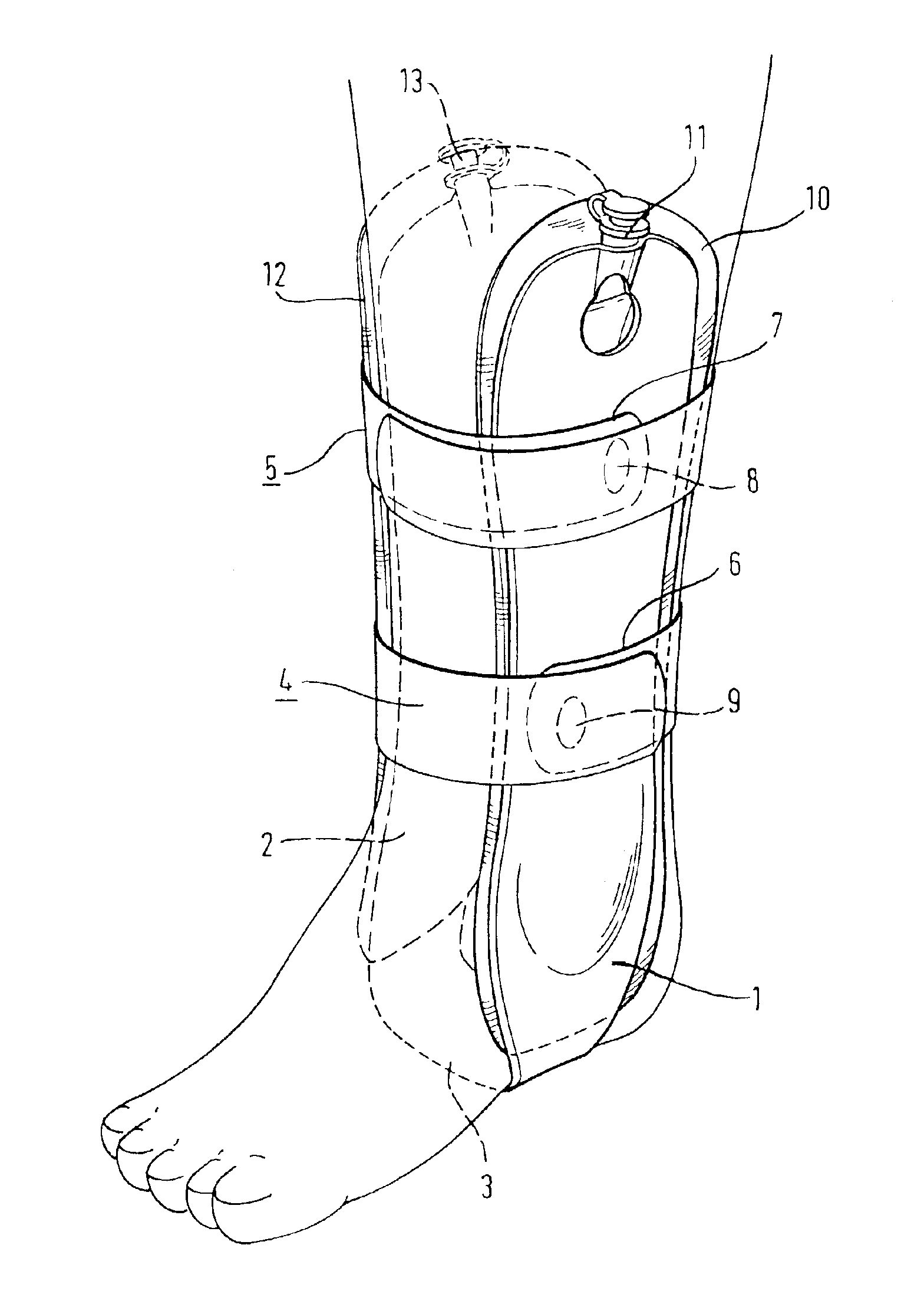
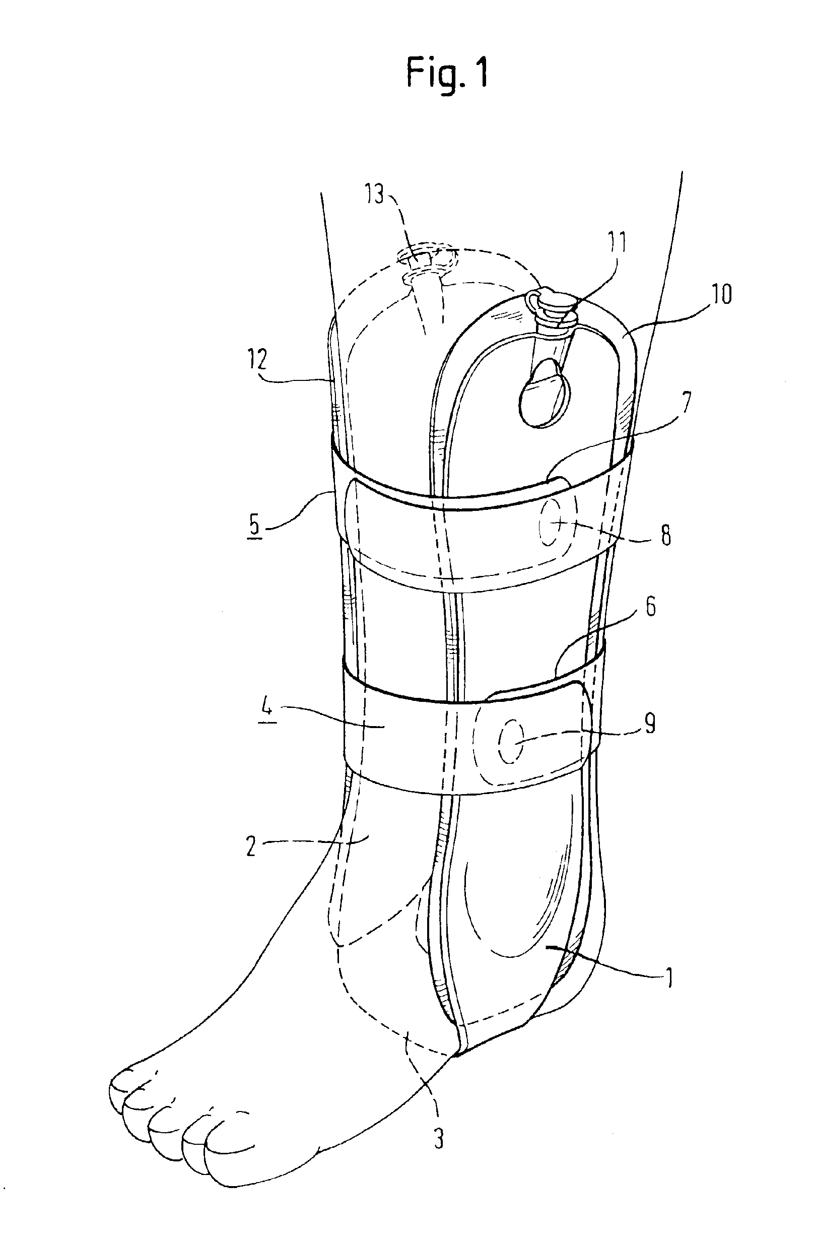
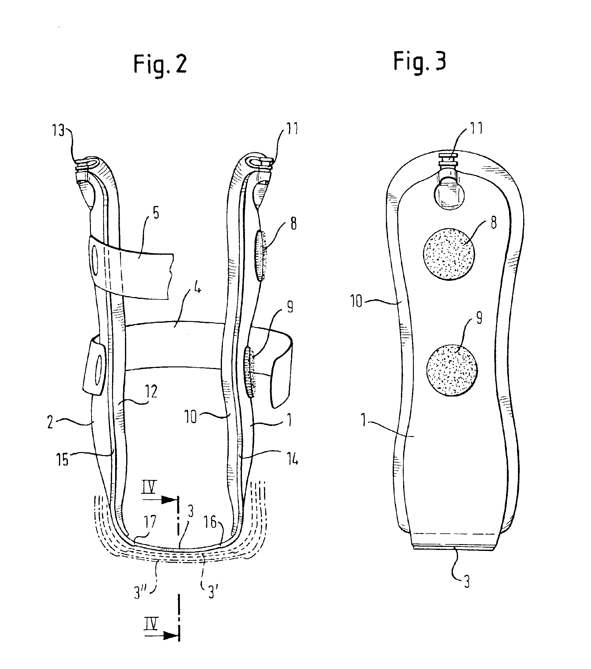
The ankle brace fitted to a foot in FIG. 1 comprises the two arms 1 and 2 which extend from the sole of the foot towards the knee and which are joined in the region of the sole of the foot by the connecting member 3 (invisible in FIG. 1). The design and function of the connecting member 3 will be discussed in greater detail in connection with FIG. 2. The ankle brace with its two arms 1 and 2 is fixed in place by the two tapes 4 and 5 which are fixed to the arm 2 and which overlap in the region of the arm 1. The bottom parts 6 and 7 are furnished with Velcro parts 8 and 9 which interact in known manner with corresponding parts on the inner sides of the overlapping ends of the tapes 4 and 5. This manner of fixing of an ankle brace equipped with two arms is known.

The arm 1 is joined to the continuous cushioning chamber 10 which, with the ankle brace fitted, lies between the arm 1 and the leg of the wearer. The cushioning chamber 10 is inflated via th...


PUM


Abstract

Ankle brace with two arms extending over the ankle bones along the lower leg, said arms being joined under the foot by a flexible connecting member and being provided with cushioning chambers containing a fluid, each arm of the brace being provided with a single cushioning chamber with a longitudinal subdivision, said longitudinal subdivision forming a zone of reduced expandability in the region of the ankle bone and therefore forming opposite the ankle bone a recess which receives the latter, the connecting member being made of a material of such tensile elasticity that, during walking and the accompanying rolling of the foot as well as rhythmic pumping of the cushioning chambers, said connecting member is intermittently lengthened and shortened.

Description

FIELD OF THE INVENTIONThe invention relates to an ankle brace with two arms extending over the ankle bones along the lower leg, said arms being joined under the foot by a flexible connecting member and being provided with cushioning chambers containing a fluid.BACKGROUND OF THE INVENTIONSuch an ankle brace is presented and described in U.S. Pat. No. 5,125,400. More particularly, the said patent specification relates to ankle braces in which each arm of the brace has a plurality of cushioning chambers separately inflatable through their own valves, the two arms being joined by a simply flexible connecting member of Velcro material. Furthermore, the patent specification also refers to earlier ankle braces which had only one cushioning chamber on each arm. According to the information in the patent specification, however, the use of only one cushioning chamber resulted in high pressures outside the region of the ankle.SUMMARY OF THE INVENTIONThe object of the invention is to create an ...

Claims


Application Information

Patent Timeline
IPC IPC(8): A61F5/01
CPCA61F5/012A61F5/0111
Inventor REINHARDT, HOLGER
Owner BAUERFEIND GMBH & CO
Why Eureka
Try Eureka