Walking stick

Inactive Publication Date: 2010-05-20
LAH JEH KUN
View PDF12 Cites 23 Cited by
  • Summary
  • Abstract
  • Description
  • Claims
  • Application Information

AI Technical Summary

Benefits of technology

[0027]In the walking stick according to the embodiment, since the two button members are provided in the opposite direction and are connected to the lower connecting pipe and the upper connecting pipe at the same time during locking, the impact is distributed and the surface pressures applied to each button member and each through hole are decreased so that the deformations of th

Problems solved by technology

During the use of the walking stick, there may be a case where the walking stick cannot be used anymore due to various problems.
The impact is directly transmitted to the locking device or to the connecting pipe through the locking device, and due to the impacts, many portions between the locking devices and the connecting pipes are damaged as the walking stick is used.
In addition, due to unexpected situations such as a case where a foreign material penetrates into the button or a case where the hole into which the button is inserted is deformed by a sharp impact, the operations of the spring 42 and the button 41 may be problematic, and the walking stick itself may not be used anymore.
If such a situation occurs during mountain climbing or sports activities or

Method used


Image

  • Walking stick
  • Walking stick
  • Walking stick

Examples


Example

Embodiment 1

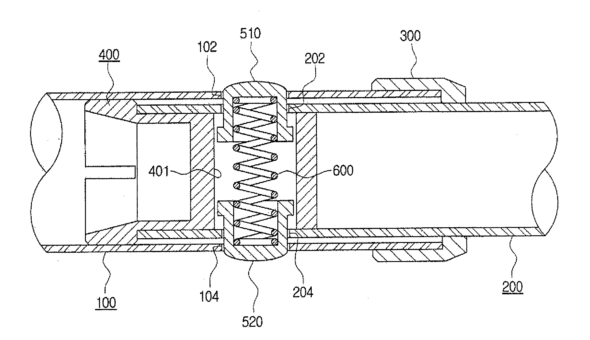
[0047]FIGS. 3, 4, 5, and 6 illustrate a locking device portion according to an embodiment. FIG. 3 is a cross-sectional view, FIG. 4 is a transverse cross-sectional view, FIG. 5 is a cross-sectional view of a state in which locking is released by pushing a button member, and FIG. 6 is a transverse cross-sectional view of FIG. 5.

[0048]As illustrated In FIGS. 3 and 4, into an upper connecting pipe 100 a lower connecting pipe 200 having a smaller diameter is inserted.

[0049]First and second through-holes 202 and 204 are provided in both sides of the lower connecting pipe 200 in a transverse direction (radial direction), and first and second button members 510 and 520 are inserted into the first and second through-holes 202 and 204 so as to slide in the opposite directions. A single spring 600 is provided inside the first and second button members 510 and 520 so as to elastically support the first and second members 510 and 520 in the radial direction.

[0050]Third and fourth th...

Example

Embodiment 2

[0057]FIGS. 7 to 9 and FIGS. 10 to 12 are enlarged views of a locking device portion according to another embodiment. FIG. 7 is a cross-sectional view, FIG. 8 is a transverse cross-sectional view taken along the line A-A of FIG. 7, FIG. 9 is a transverse cross-sectional view taken along the line B-B of FIG. 7, FIG. 10 is a view illustrating a state where locking is released by pushing a button member in FIG. 7, FIG. 11 is a transverse cross-sectional view taken along the line C-C of FIG. 10, and FIG. 12 is a transverse cross-sectional view taken along the line D-D of FIG. 10.

[0058]As compared with the above-described embodiment, in the walking stick according to this embodiment, two button members are spaced from each other to improve convenience for use and stability for operations.

[0059]As illustrated in FIGS. 7 to 9, in a lower connecting pipe 250, first and second through-holes 252 and 254 are provided to be opposed to each other at a predetermined interval in a long...


PUM


Abstract

Provided is a walking stick having a pole configured by a plurality of connecting pipes. The walking stick includes: an upper connecting pipe; and a lower connecting pipe inserted into the upper connecting pipe, wherein first and second through-holes are provided in both sides of the lower connecting pipe at opposing positions to each other, first and second button members are slidably inserted into the first and the second through-holes, respectively, a spring for elastically supporting the first and the second button members in a radial direction is provided inside the first and the second button members, and third and fourth through-holes are provided in the upper connecting pipe at positions corresponding to the first and the second through-holes of the lower connecting pipe so that the first and the second button members are moved in and out through the first to the fourth through-holes.

Description

CROSS-REFERENCE TO RELATED APPLICATION[0001]This application claims priority to Korean Utility Model Application No. 20-2008-0015410, filed on Nov. 19, 2008, and all the benefits accruing therefrom under 35 U.S.C. §119, the contents of which in its entirety are herein incorporated by reference.BACKGROUND[0002]1. Field[0003]This disclosure relates to a walking stick having a pole configured by connecting a plurality of connecting pipes, and more particularly, to a walking stick capable of actively managing a malfunction of a locking device and minimizing deformation of connecting pipes and the locking device by distributing impacts.[0004]2. Description of the Related Art[0005]In general, a walking stick is used by many people for climbing and sports activities or by patients for walking. The walking stick includes a pole and a handle provided to an end portion of the pole. The pole is generally configured by connecting a plurality of connection pipes so as to be folded in a longitudi...

Claims


Application Information

Patent Timeline
IPC IPC(8): A45B9/00
CPCA45B2009/007A45B9/00
Inventor LAH, JEH-KUN
Owner LAH JEH KUN
Why Eureka
Try Eureka