Vehicle Seat

Active Publication Date: 2018-10-04
TS TECH CO LTD
View PDF0 Cites 0 Cited by
  • Summary
  • Abstract
  • Description
  • Claims
  • Application Information

AI Technical Summary

Benefits of technology

The present invention aims to provide a vehicle seat that is attached to the floor of a vehicle via a rail device and a coupling device. The new design provides a high level of stiffness, which minimizes deformation of the rail device and the coupling device without adding significant weight or cost to the seat.

Problems solved by technology

Therefore, the weight and the manufacturing cost of the seat inevitably increase.

Method used


Image

  • Vehicle Seat
  • Vehicle Seat
  • Vehicle Seat

Examples


Embodiment Construction

)

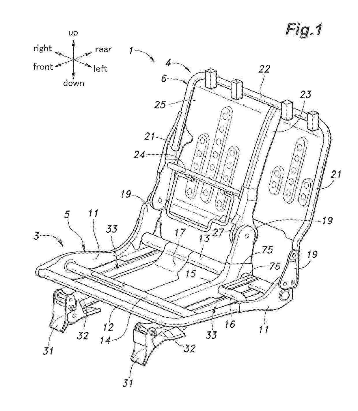
[0027]A vehicle rear seat (which may be a second row seat or a third row seat) according to an embodiment of the present invention is described in the following with reference to the appended drawings. The seat is configured to change the state and the position thereof between a use position (seating position) and a storage position, and the following description is based on the use position of the vehicle seat unless otherwise specified.

[0028]As shown in FIG. 1, the seat 1 serves as the right seat and the center seat of the second row seat or the third row seat of a motor vehicle. The seat 1 includes a seat cushion 3 rotatably provided on a floor F of the vehicle and a seat back 4 rotatably supported by the seat cushion 3. The seat cushion 3 and the seat back 4 are provided with a seat cushion frame 5 and a seat back frame 6, respectively, as a skeletal frame. The seat cushion 3 and the seat back 4 are provided with pads (not shown in the drawings) supported by the seat cushion fr...


PUM


Abstract

Provided is a vehicle seat which is attached to a floor of a vehicle via a rail device and a coupling device with a high level of stiffness so as to minimize deformation of the rail device and the coupling device without substantially increasing the weight and the manufacturing cost of the seat. The vehicle seat is provided with an upper engagement portion secured to a member on a side of an upper rail of the rail device, and a lower engagement portion secured to a member on a side of a lower rail of the rail device and including a part opposing a corresponding part of the upper engagement portion from above defining a prescribed gap therebetween. The coupling device is provided laterally spaced from the rail device, and the upper engagement portion and the lower engagement portion are provided substantially directly above the coupling device.

Description

TECHNICAL FIELD[0001]The present invention relates to a vehicle seat.BACKGROUND ART[0002]A known vehicle seat comprises a lower rail having a front end pivotally attached to a floor of the vehicle, an upper rail slidably engaged by the lower rail and fixedly secured to a seat cushion frame, and a coupling device provided on a rear end of the lower rail and configured to detachably engage a striker fixedly secured to the floor. See JP2005-53246A, for instance. This vehicle can be pivoted between a use position and a storage position around the front end of the lower rail once the striker is released from the coupling device.[0003]In such a seat, to minimize deformation of the rail device and the coupling device under the inertia force created at the time of a vehicle crash, the rail device and the coupling device are required to be built with a high level of stiffness. Therefore, the weight and the manufacturing cost of the seat inevitably increase.SUMMARY OF THE INVENTION[0004]In vi...

Claims


Application Information

Patent Timeline
IPC IPC(8): B60N2/08
CPCB60N2/0825B60N2/085B60N2/3009B60N2/427B60N2/68
Inventor IKAWA, HARUKIABE, YASUTAKA
Owner TS TECH CO LTD
Why Eureka
Try Eureka